4 – ENGLISH
INSTALLATION
3
3 INSTALLATION
3.1 PRE-INSTALLATION CHECKS
a
The installation must be carried out by qualied
personnel in compliance with the current legislation,
standards and regulations, and with the instructions
provided in this manual.
Before proceeding with the product’s installation, it is necessary
to:
– check the integrity of the supply
– check that all the materials are in good working order and
suited to the intended use
– make sure that the structure of the gate is suitable for being
automated
– make sure that the weight and dimensions of the gate leaf
fall within the operating limits specied in the “Product usage
limits” paragraph
– check that the installation location is compatible with the
overall clearance of the product (see “Figure 5“)
– make sure that there is enough space in the installation
location for the gearmotor’s arm to rotate fully (see “Figure 2“)
2
– verify that there are no points of greater friction during the
opening and closing movements along the entire gate path
– verify that the overrun mechanical stops are sturdy enough
and that they do not deform even if the leaf should strike them
forcefully
– verify that the gate leaf is well balanced: it must not move by
itself when left in any position
– make sure that the installation area is not subject to ooding; if
necessary, the product must be installed appropriately raised
above ground level
– verify that the area where the gearmotor is installed allows for
unlocking the latter and manoeuvring easily and safely
– verify that the mounting positions of the various devices are
protected against impacts and that the mounting surfaces are
sufciently sturdy
– prevent any parts of the automation from being immersed in
water or other liquids
– keep the product away from heat sources and open ames and
acid, saline or potentially explosive atmospheres; these may
damage the product and cause malfunctions or dangerous
situations
– if there is an access door in the gate, or within its range of
movement, make sure that it does not obstruct the gate’s
normal path; install an appropriate interlock system if
necessary
– connect the control unit to an electricity supply line equipped
with a safety earthing system
– connect the gate to the earthing device in accordance with
the current legislation
– include a device on the electric power line ensuring
complete disconnection of the automation from the grid. The
disconnection device must have contacts with a sufcient
gap to ensure complete disconnection, under the Category
III overvoltage conditions, in accordance with the installation
instructions. Should it be necessary, this device guarantees
fast and safe disconnection from the power supply; it must
therefore be positioned in view of the automation. If placed in
a non-visible location, it must have a system that blocks any
accidental on unauthorised reconnection of the power supply,
in order to prevent dangerous situations. The disconnection
device is not supplied with the product.
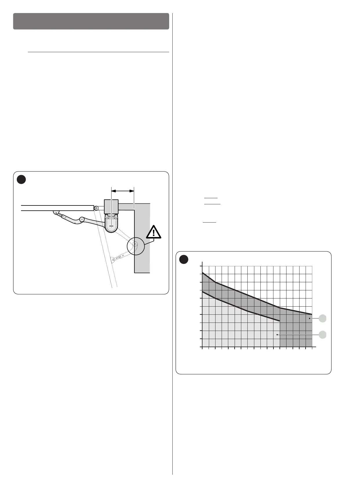
3.2 PRODUCT USAGE LIMITS
Carry out the following checks before installing the gearmotor:
– check that the leaf to be automated falls within the specied
values (see “Figure 3“)
– maximumwidth of the leaf: 3,5 m (with weight up to 200 kg)
– maximumweight of the leaf: 330 kg (with width up to 1,8 m)
– verify the limits for the values shown in the “TECHNICAL
SPECIFICATIONS” chapter
– minimumwidthof the space reserved for the gearmotor’s
installation: 210 mm
– the arm’s xing bracket must be attached to a sturdy point of
the leaf (for example, the frame), to guarantee solid and safe
anchoring.
150
1,8 2,0 2,2 2,4 2,6 2,8 3,0 3,2 3,4
200
100
250
300
350
Leaf weight (kg)
Width of the leaf (m)
A
B
3
A For arm with FULL length
B For arm with REDUCED length

 Loading...


