ENGLISH – 27
Table 11
SIGNALS OF LED (L1..L4) (“FIGURE 54”)
Status Meaning Possible solution
LEDs L1 - L2
Slow ashing
Change in the number of
devices connected to the
“BlueBus” or learning of
the device not executed.
It is necessary to run the device learning procedure (refer to the “Device
learning” paragraph)
LEDs L3 - L4
Slow ashing
The positions of the
mechanical stops were
never learned or after
the mechanical stop
learning procedure, the
dip-switch conguration
changed.
It is necessary to run the device learning procedure (refer to the “Device
learning” paragraph)
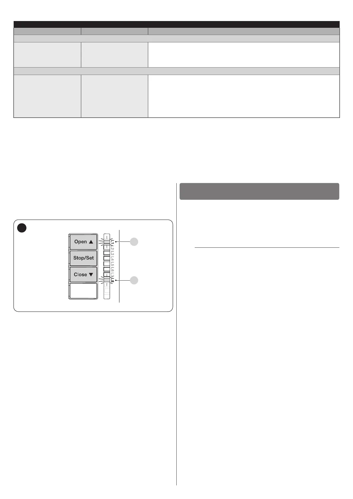
8.3 ANOMALY LOG
The control unit can display any anomalies that have occurred
in the last 8 manoeuvres (for example, the interruption of a
manoeuvre due to the intervention of a photocell or sensitive
edge).
L1
L8
55
To check the list of anomalies:
1. press and hold the
g
button for roughly 3 seconds
2. release the
g
button when the “L1” LED starts
ashing
3. press and release the
f
or
h
button to
shift ashing of the LED to “L8” (“Anomaly list” parameter)
4. keep the
g
button pressed down (it must be kept
pressed throughout phases 5 and 6)
5. wait roughly 3 seconds, after which LED “L1” –
corresponding to the outcome of the last manoeuvre – will
light up
6. press and hold the
f
or
h
button to select
the desired manoeuvre: the corresponding LED will emit
the same number of ashes as those normally emitted by
the warning light after an anomaly (see “Table 9”)
7. release the
g
button.
FURTHER INFORMATION
(Accessories)
9
9.1 ADDING OR REMOVING DEVICES
Once the automation has been assembled, it is possible to
add or remove devices at any time. In particular, various types
of devices can be connected to the “BlueBUS” and “STOP”
inputs, as described in the following paragraphs.
m
After having added or removed devices, these must
be learned as described in the “Learning of other
devices” paragraph.
9.1.1 BlueBUS
BlueBUS is a technique that allows for connecting compatible
devices with only two wires which carry the electrical power and
the communication signals. All devices are connected in parallel
on the same 2 BlueBUS wires and without having to observe the
polarities; each device is recognised because it is assigned a
univocal address during the installation phase.
The following devices can be connected to the BlueBUS:
photocells, safety devices, control buttons, signalling lights,
etc. The control unit recognises all the connected devices
individually through an appropriate learning phase, and can
detect all possible anomalies with absolute precision.
For this reason, whenever a device is connected to or removed
from BlueBUS, the learning phase must be carried out on the
control unit, as described in the “Learning of other devices”
paragraph.

 Loading...


