ENGLISH – 7
Before starting the installation, it is necessary to determine
the length of the gearmotor arm – refer to the paragraph “
Determining the length of the gearmotor arm”.
3.5.1 Determining the length of the gearmotor arm
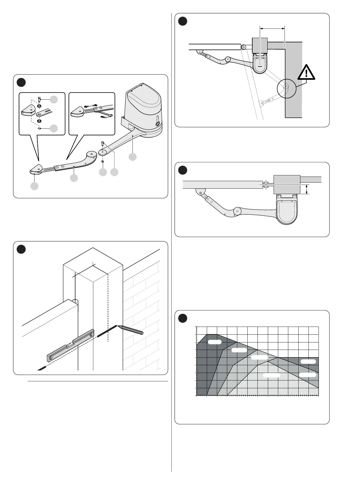
Assemble the components making up the motor arm::
1. attach the curved arm (A) to the straight arm (B) using the
pin (C) and retaining ring (D). likewise, attach the xing
bracket for the gate leaf (E) to the curved arm (A)
B
D
C
A
C
D
7
2. to dene the position of the gearmotor VERTICALLY,
draw a horizontal line on the pillar at the same height at
which the arm’s xing bracket will be on the leaf, after the
installation
3. dene the position of the gearmotor HORIZONTALLY
[level A].
A
8
a
If there is a xed obstacle (wall, tree, etc.) near the
installation area, measure distance E then proceed
as follows:
– If distance (E) is equal to or above 650 mm, consult
the paragraph “Installing the gearmotor with FULL-
LENGTH ARM”
– If distance (E) is between 300 mm (minimum) and 650
mm (maximum), consult the paragraph “Installing the
gearmotor with REDUCED-LENGTH ARM”.
9
3.5.2 Installing the gearmotor with FULL-LENGTH ARM
To install HYKE:
1. measure the distance (B)
B
10
2. move the leaf to the desired maximum opening position
(maximum 110°) and check the resulting opening angle
3. mark the resulting distance (B) on the graph and, from
this point, draw a horizontal line intersecting the area that
includes the value of the measured opening angle
4. in the points of intersection between the horizontal line
and the area, draw a few vertical lines to determine the
values that can be used for level (A); choose in this range
a value for level (A). For example: if (B) is 200 mm and the
desired angle is 110°, level (A) will be between 300 mm
and 345 mm
0
150 175 200 225 250 275 300 325 350 400375 425
50
100
150
200
250
300
350
400
90°-95°
95°-100°
100°-105°
105°-110°
95°-105°
90°-95°
11

 Loading...


