31
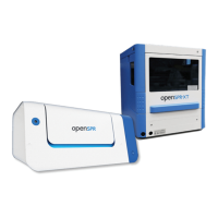
Figure 2.10 – Placing Sensor Holder into Instrument by slowly bringing it into contact with the Fluidics Block
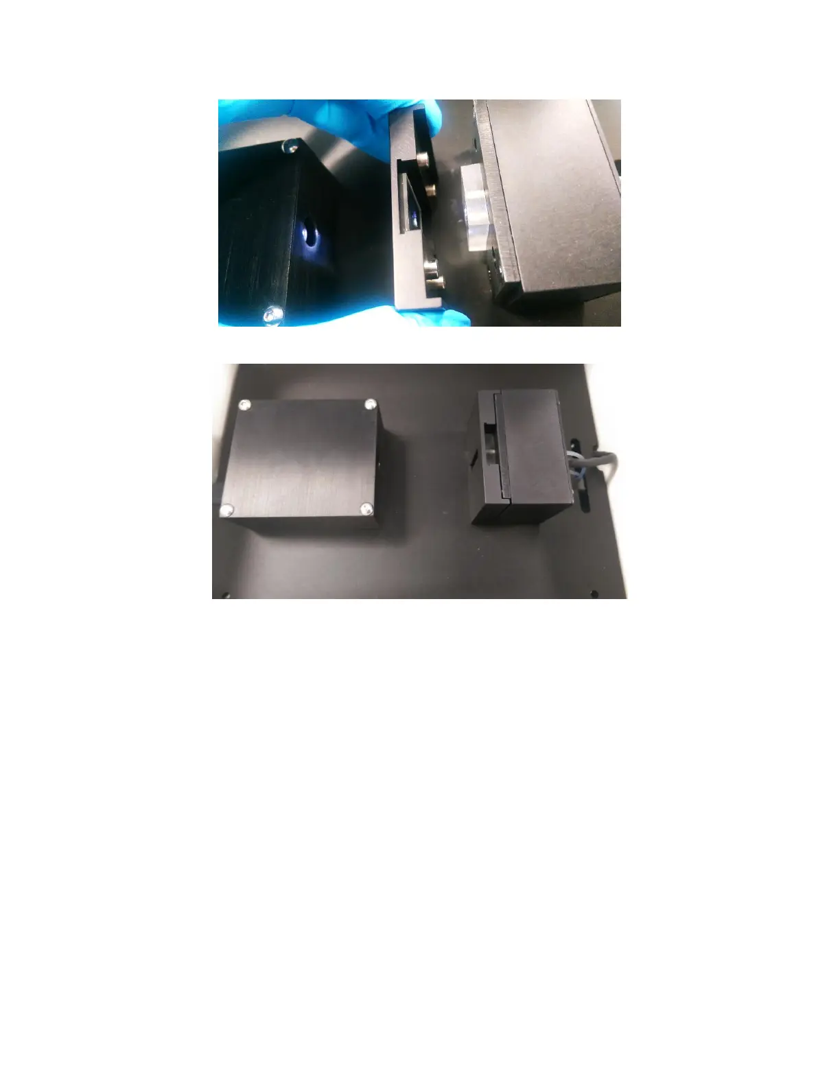
Figure 2.11 - Properly secured sample holder onto Fluidics Block
7. After the Sensor Chip has been loaded, select “Yes” to activate the pump and fill the Flow Cell
with running buffer [Figure 2.7]. A progress bar will show the progress of the filling process.
The pump will now continue to run at full speed unless manually stopped or changed.
You will now see that the Absorbance graph no longer shows a flat line. It will display a strong
Gaussian shaped absorbance peak [Figure 2.12]. This is the LSPR peak of the Sensor Chip.