14 - FORM NO. 56043098 - Convertamatic
™
24, 26, 28, 32 / BA 625, 725, 825
SOLUTION SYSTEM
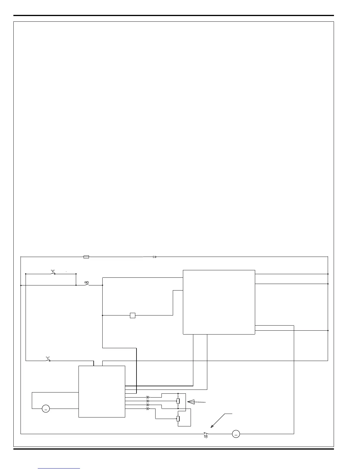
CIRCUIT OVERVIEW SOLUTION AUTO MODE (SOLENOID VALVE CIRCUIT)
See Figure 2.
+ (Positive) circuit input starts with:
• A closed S3 key switch will direct the needed positive voltage (BRN wires) to the L1 solenoid coil and A1 control board terminal #J1-13.
- (Negative) circuit input starts with:
• A battery negative ground input at the A1 control board terminal #B2 (J1-9)
• The A1 control board solution button enabled.
• A negative voltage output from the A2 speed controller’s (pin #6) Red/Blk wire to the A1 control board Red/Blk wire (terminal J1-5). Note: The A2 speed controls
brake output (pin #6) occurs whenever the R1 direction throttle pot is moved off its neutral setting.
• A negative voltage output from the A1 board’s terminal J1-11 Red/Grn wire is direct to the L1 solenoid coil turning it on to allow fl ow through the valve body.
CIRCUIT OVERVIEW SOLUTION AUTO MODE (SOLUTION PUMP CIRCUIT)
See Figure 2.
+ (Positive) circuit input starts with:
• With the batteries connected the needed positive voltage (Red wires) to the M7 Solution Pump.
- (Negative) circuit input starts with:
• A battery negative ground input at the A1 control board terminal #B4 (J2-6)
• The A1 control board solution button enabled.
• A negative voltage output from the A2 speed controller’s (pin #6) Red/Blk wire to the A1 control board Red/Blk wire (terminal J1-5). Note: The A2 speed controls
brake output (pin #6) occurs whenever the R1 direction throttle pot is moved off its neutral setting.
• A negative voltage output from the A1 board’s terminal J1-8 Grn/Blk wire is direct to the M7 Solution Pump turning it on to allow fl ow to the L1 Water Valve
Solenoid. NOTE: The solution pump’s output volume is controlled by the A1 board’s programmable capability and changes the pulsing of the negative battery
connection to the pump.
Electrical Diagram
*For complete description of all callouts see Electrical System Wiring Diagram.
FIGURE 2
S1
M7
SOLUTIONPUMP
M
12
-+
GRN/BLK
RED
NOTE:SWITCHISPARTOF
PUMPASSEMBLY
R1
POT.5KOHMTHROTTLE
R2
POT.100KOHMSPEEDLIMIT
S3
SW,SPSTKEY
M1
MOTOR,WHEELDRIVE
M
F3
CIRCUITBREAKER,30AMP
F2
CIRCUITBREAKER,5AMP
L1
COIL,SOLUTIONSOLENOID
1
2
3
1
2
3
12
12
12
WHT
BRN/BLK
YEL/RED
RED
GRN
BRN
BLU
BLK
RED/BLK
BRN
RED/BLK
WHT/YEL
BRN
RED/GRN
RED
BLU/BLK
BLK
GRN/BLK
BLK
BLK
BLK
BLU/BLK
BRN
WHT
BLU
BLK
BRN
WHT
BLK
+-
B+1
SOLUTION
FOR/REV.
J1-13
J1-11
REVERSE
B-1
SOL.PUMP
B-4
B-2
A1
CONTROLBOARD
J1-5
J1-6
J1-7
J1-8
J2-6
J1-9
A2
B+ B-
1210SPEEDCONTROLLER
M1
M2
PIN3-POT.HI
PIN4-POT.WIPER
PIN13-POT.LO
PIN5-KSI
PIN16-REV
PIN6-BRAKE(-)
(1228FOR36V)
PIN9-STATUS
PIN18-SPEEDLIMITPOT
F1
FUSE,150A.
BT1
BATTERY
12
+-
RED
RED
BLK
24VDCOR36VDC

 Loading...