FORM NO. 56043098 - Convertamatic
™
24, 26, 28, 32 / BA 625, 725, 825 - 39
WHEEL DRIVE SYSTEM
GENERAL FUNCTIONAL OVERVIEW
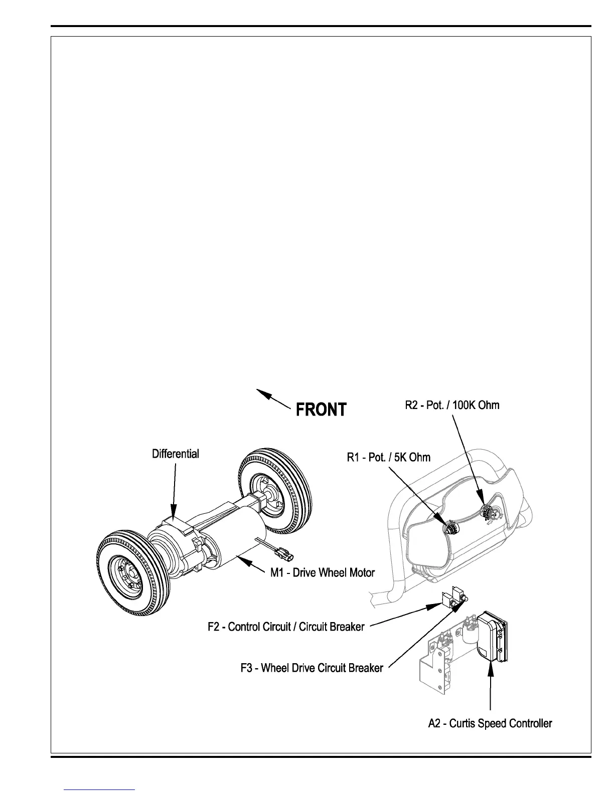
See Figures 1 and 2. A 300 watt (.4 HP) permanent magnet (24V) motor transaxle (M1) is used for the wheel drive on all machines. A Curtis PMC solid state speed
controller (A2) regulates the variable speed and Fwd/Rev wheel drive motor functions. Location of the controller is in the rear handle housing electrical compartment
(accessible by removing the 4 screws securing the rear electrical panel). The potentiometer R1 mounted inside the drive paddle inputs to the A2 controller the
machine operator’s throttle (variable speed) and direction demands. A second pot R2 (knob adjusted) is located on the outside of the paddle cover and controls the
machine’s maximum transport and scrub speeds.
Drive Motor System Function
See Figures 2 and 3. With the key switch S3 closed the Brn wire inputs 24V to the A2 speed controller (Pin 5-KSI) to make its internal control circuits operational
(powering it up). The F3 circuit breaker (30 Amp) supplies the positive load circuit voltage input to the B+ controller terminal (Wht/Yel wire). The black wire from the
battery negative standoff supplies the (NEG.) input to the B- controller terminal.
Moving the 5K Ohm R1 pot off its centered balanced neutral setting of approximately 2500 Ohms, activates the operator input to the speed control. Forward or
Reverse movement of the drive paddle rotates the pot shaft and the pot’s variable resistance values are changed, which generates the internal voltage signals
(0-5Volts) needed for the controller’s output operation. These control board voltage input signals are what energizes the Fwd and Rev directional relays, which then
selects the motor polarity and fi nal voltage level outputs at the M1 & M2 terminals.
When the operator turns the R2 speed limit Pot from min. to max. (CW) this causes an input resistance relationship change between the pot high (+) and wiper
terminals (high to low Ohms) thus increasing the maximum wheel motor operating speed range. Turning the knob (CCW) increases the resistance and the motor
speed range is reduced.
FIGURE 1

 Loading...