FORM NO. 56043098 - Convertamatic
™
24, 26, 28, 32 / BA 625, 725, 825 - 49
ELECTRICAL SYSTEM
SPECIFIC WET CELL BATTERY INFORMATION
Wet Cell Battery specifi cations
- Use a combination of multiple 2-volt cell units to construct a 24 Volt DC battery pack system.
- Nilfi sk-Advance recommended battery pack capacity is a 238 AH @ 20 Hour Rate deep cycle battery system. Note: The battery pack must fi t the battery
compartment size listed in Specifi cations.
Wet Cell Battery Charger Specifi cations
- Use a 24 Volt DC output charger matching the DC battery pack voltage and the input AC line voltage supply being used.
- When selecting a battery charger always follow the recommendation of the battery supplier to match the proper charger DC output amperage to the amp/hour rating
batteries being installed. This will prevent the battery pack from being over or under charged.
- The recommended 238 AH battery should be matched to a 24V, 25 Amp output charger on machines using (4) 6V batteries.
DESCRIPTION OF THE LOW VOLTAGE CUTOUT FEATURE
All models discussed in this manual are equipped with a low voltage cutout feature to prevent over-discharging of the batteries. When a machine’s battery pack
voltage falls below specifi cally defi ned thresholds (voltage settings) the scrub system is automatically shut down. The cutout level is adjustable. The standard lead
acid battery (wet cell) setting is 1.72V per cell and alternate maintenance free battery (gel cell) setting is 1.81V per cell. The standard setting is factory selected and
should be used unless the battery manufacturer specifi es the higher cutout voltage.
Special Service Note: On all the 24V machines a minimum recharge voltage of 2.13 volts per cell must be reached to allow the scrub brush and solution system to
(reset) function again. A 24V-battery pack must increase to a 25.6-volt minimum.
DESCRIPTION OF THE BATTERY CONDITION INDICATORS
The Battery Condition Indicator will give an indication of the state of charge of the batteries, 5 vertical bars indicates a fully charged battery after a complete charging
cycle. The battery condition indicator will retain the state-of-charge even if the key has been turned off. The state-of-charge indication is reset to full charge when
the batteries have been recharged. It is also possible to choose between two different low voltage thresholds depending on whether maintenance free or standard
batteries are being used (have qualifi ed service engineer perform this selection*). NOTE: The following percentages are based on useable battery capacity
not total battery capacity. Therefore, 100% discharge = 80% of total battery capacity for standard wet cell batteries or 70% of total battery capacity for maintenance
free batteries.
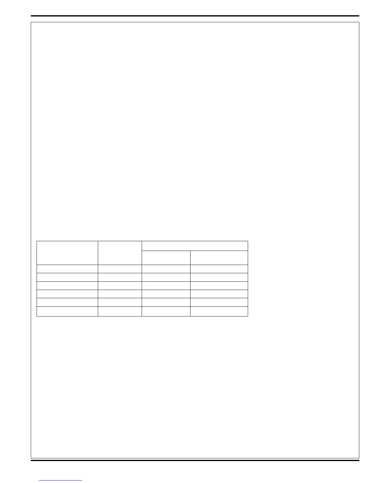
Explanation of Battery Indicator Lights and Voltage Ranges
24 volt machines
% of
Battery Indicator Discharge Standard Alternate
5 vertical indicator bars Full to 50% 22.6+ 23.0+
4 vertical indicator bars 50% to 75% 22.0-22.6 22.6-23.0
3 vertical indicator bars 75% to 90% 21.3-22.0 22.3-22.6
2 vertical indicator bars 90% to 95% 21.0-21.3 22.0-22.3
1 vertical indicator bars 95% to 99% 20.6-21.0 21.6-22.0
0 vertical indicator bars 100% <20.6 <21.6
*Important Note: See the Main Control Board Special Program Options manual section (located in the Electrical System) and follow the instructions for changing
the low voltage cutout threshold.
 Loading...