FORM NO. 56043098 - Convertamatic
™
24, 26, 28, 32 / BA 625, 725, 825 - 13
SOLUTION SYSTEM
FUNCTIONAL OVERVIEW
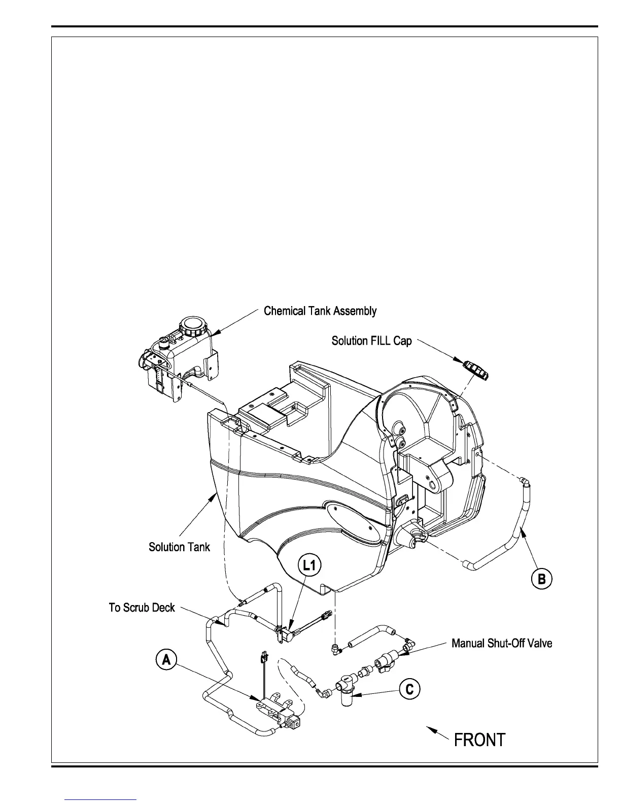
See Figure 1. The Convertamatic / BA 625 series models have a solution tank fi ll capacity of 20-gallons (76 liters). All models use one right rear tank fi ll opening,
which offers ease of fi lling. Plumbed into the manual solution shut off valve outlet is a serviceable Solution Filter (C), to keep debris from entering the solenoid valve.
Also fi tted to the tank is a fl exible Clear Hose (B) used to indicate the solution level and to drain the tank for system maintenance.
The standard solution system uses an electrical Solenoid Valve (L1) which stops and starts the solution fl ow to the scrub brushes. The M7 water pump (A) located on
the machine chassis controls the needed fl ow volume demand to the scrub brushes. See Electrical Diagram Figure 2. The electrical circuit that turns on (energizes)
the solenoid coil and water pump is activated through the (A1) control panel’s solution switch button input and the FWD / REV (A2) Speed Controller voltage output
signals. Note: See the Know Your Machine section in this manual for a complete explanation of the solution operation modes.
During normal machine scrubbing the solution system’s Auto Mode is selected and works in conjunction with the wheel drive speed controller and the (A1) main
controller’s scrub system outputs to turn On & Off the (L1) solenoid valve and pump. The solution will fl ow to the scrub brushes when the scrub deck is lowered and
the handle drive paddle (box) is pushed Fwd. Note: When the solution On/Off button is turned Off, no fl ow can occur while the machine scrub deck is down and the
drive paddle activated.
*Note: Figure 1 shows the solution components of a machine with the Chemical System. The Chemical Tank Assembly is not found on all models.
FIGURE 1
revised 5/07
 Loading...