FORM NO. 56043098 - Convertamatic
™
24, 26, 28, 32 / BA 625, 725, 825 - 21
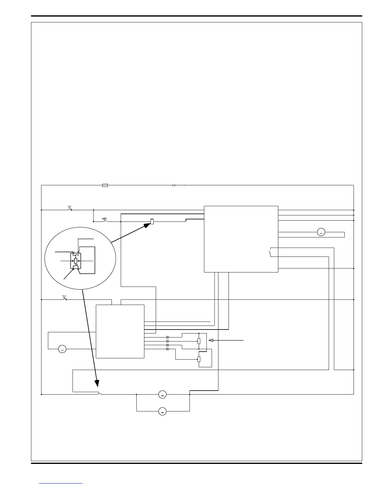
SCRUB SYSTEM
• Scrub Brush Removal Function (Continued / Disc only)
• Control and Load circuit detail.
A closed S3 key switch supplies the needed positive voltage to the K1 brush solenoid coil, A1 control board (J1-13) Brn wire and K3 brush remove coil relay
(Part of A1 Control Board).
- The brush remove circuit sequence starts when the operator depresses the control panel scrub off button (H) for 2-3 seconds activating the A1 board’s brush
remove function. This triggers (starts) an internal timer relay closing the K1 coil ground circuit, pin (J1-14) Vio/Blk wire turning on momentarily the brush
solenoid to run the brush motors.
- Simultaneously with the K1 coil being turned on the same input command closes the K3 coil (Part of A1 Control Board) turning it ON.
- This pulls in the K3 load contacts (Part of A1 Control Board) connecting it to the battery ground through the A1 Brush Remove circuit N.O. Blk wire and Common
Blu/Wht wire to K1 Load Contactor N.C
- The next step is the board timer turning off the K1 brush solenoid and connecting the normally Pos. motor load circuit to a battery ground, sending a neg.
voltage from the K3 Relay (Part of A1 Control Board) though the Blu/Wht N.O. wire. When K1 is de-energized the neg. voltage from the K3 relay is connected
to the Brush Motors Positive Wht. wires through a Red/Wht jumper wire connected to the K1 N.C.
- With two battery ground inputs at the brush motors this circuit causes a short to ground and the motors stop abruptly. The built up brushes inertia easily spins
the brushes off the motors drive disc lugs.
FIGURE 1
COIL
BRUSH MOTOR CONTACTOR
F1
FUSE,150A.
BT1
BATTERY
F2
12
+-
RED
RED
BLK
24VDC OR 36VDC
A1
CONTROLBOARD
B-
J1-3
J2-3
J2-2
M2
MOTOR, LEFT BRUSH
M
M3
MOTOR, RIGHT BRUSH
M
R1
POT.5KOHMTHROTTLE
R2
POT. 100K OHM SPEED LIMIT
S3
SW,SPSTKEY
M1
MOTOR, WHEEL DRIVE
M
K1
F3
CIRCUIT BREAKER, 30AMP
M5
MOTOR, BRUSH ACTUATOR
M
CIRCUIT BREAKER, 5AMP
K1
1
2
3
1
2
3
12
12
WHT
BRN
RED
BRN/BLK
YEL/RED
VIO/YEL
RED
WHT
WHT/GRA
GRN
BLU/WHT
VIO/BLK
BLU
BLK
RED/BLK
WHT/GRN
BRN
BLU/WHT
RED/BLK
WHT/YEL
BLK
WHT
BRN
RED
WHT/GRA
WHT
BLU/BLK
BLK
BLK
BLK
BLU/WHT
BLK
BLK
ORN/BLU
BLK
BLK
BLU/BLK
BLK
BLK
BRN
WHT
BLU
BLK
BRN
WHT
BLK
+
-
-+
+
-
POLARITY FOR DISC BRUSHES
B+1
BRUSH CONTACTOR
FOR/REV.
BRUSH MOTOR SENSE
J1-13
J1-14
REVERSE
B-1
BRUSH ACTUATOR-1
BRUSH ACTUATOR-2
B-3
B-4
B-2
J1-5
J2-5
J1-6
J1-7
J2-8
J2-1
J2-6
J1-9
J2-9
RELA Y COMMON
RELAY N.O.
A2
B+ B-
1210 SPEED CONTROLLER
M1
M2
PIN3-POT.HI
PIN4-POT.WIPER
PIN13-POT.LO
PIN5-KSI
PIN16-REV
PIN6-BRAKE(-)
(1228 FOR 36V)
PIN9-STATUS
PIN18-SPEED LIMIT POT
SUPPLY
INPUT
GRN
B+2
J2-7
K1
BRN
VIO/BLK
RED/WHT
BLU/WHT
RED
WHT
K3
BRUSH
REMOVE RELAY
 Loading...