Installation
3-18
Part 1089210A04
E 2010 Nordson Corporation
RF Detector Installation
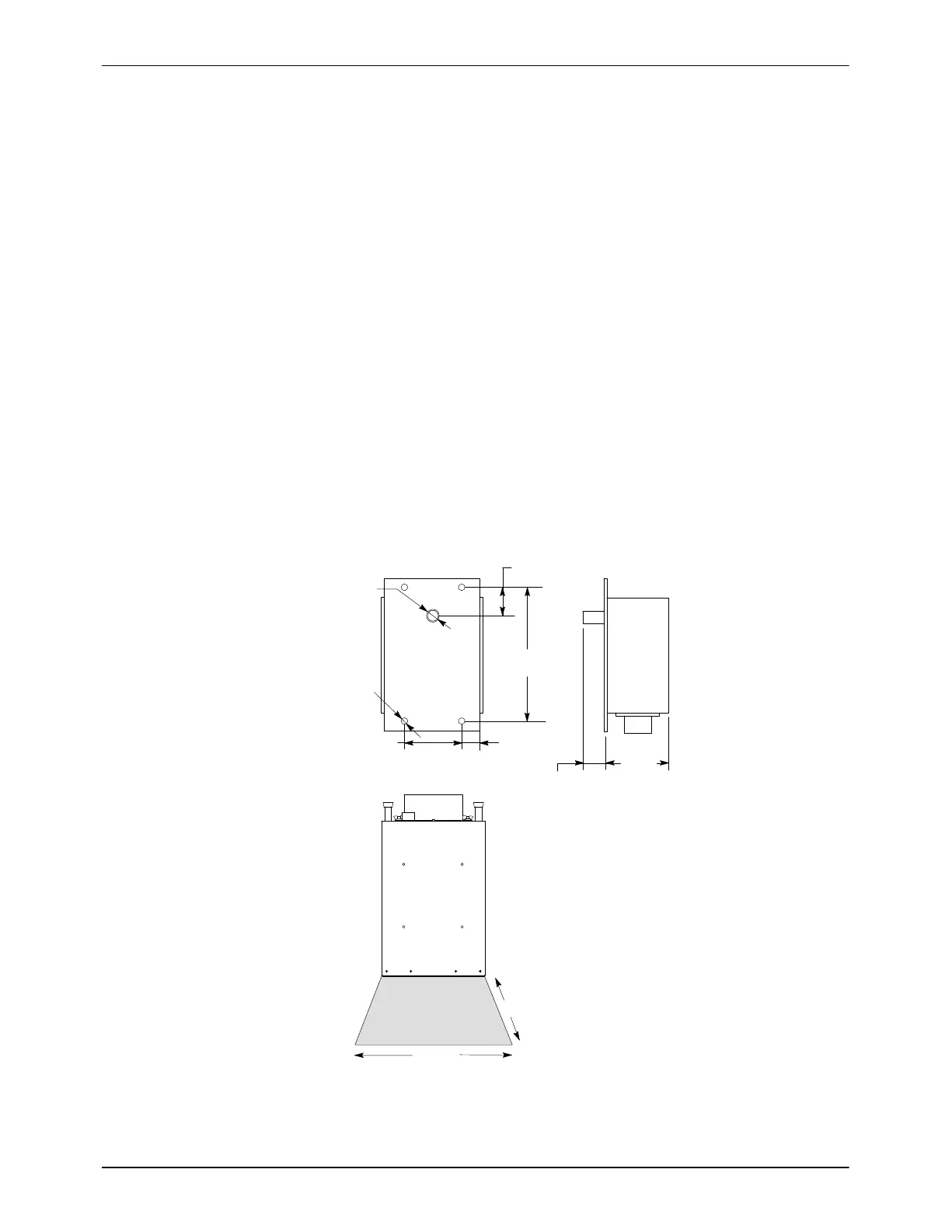
See Figures 3-3, 3-4 for RF Detector connections and 3-10 for dimensions.
S The RF detector will shut down the power supply if the lamphead RF
screen is torn or incorrectly installed. The device reacts when the RF
level is above the calibrated trip level.
S One RF detector is normally required for every 16 networked units within
one curing enclosure. However, some applications and systems may
require a RF detector on each unit. Contact your Nordson
representative for more information.
S Mount the RF detector so that the antenna faces the lamphead screen
and is between the operator and the lampheads or the lampheads and
any opening (the major source for RF leakage).
S The minimum distance should be eight inches to prevent excessive heat
on the detector surface.
S Do not mount the RF detector directly below the lamphead.
S The RF detector can be damaged when exposed to extreme RF fields.
The device has a patented self test feature to make sure the device is
working properly. If failure is detected, the unit is not serviceable and
must be replaced.
(3.50)
88.9
(1.50)
38.1
(0.50)
12.7
(0.75)
19.1
(Ø0.28)
Ø7.2
(Ø0.16)
Ø4.0
(0.55)
14.0
(1.69)
42.8
No RF Detector
305 (12)
203 (8)
Figure 3-10 RF Detector Installation