Installation
3-15
Part 1089210A04
E 2010 Nordson Corporation
Monitoring Static Pressure
See Figure 3-8. The lamphead pressure sensor can be connected to a
pressure port at the top of the lamphead or alternately to one at the bottom.
(See Figure 3-6 for the location of the pressure ports.)
Top/Front Pressure Port
If the pressure from the exhaust air from the lamphead’s internal or external
blower is not restricted in any way the top pressure port can be used.
Examples of this type of installation are when lamps are mounted in a large
enclosure without dedicated individual exhaust or quartz windows between
the lamps and the parts. Caution should be used when using the top
pressure port as any restriction of the exhaust air will fool the pressure
sensor and possibly damage the lamphead.
Bottom Pressure Port
In applications where there is a possibility of restricting the exhaust from the
lamphead, the bottom pressure port must be used. Examples of this type of
application are quartz windows, dedicated exhaust ducts, or any type of
exhaust box or lamp face attachment that can restrict the air flow. When
using the bottom pressure port the mating or mounting structure must be
designed so that this port is open to the air exiting through the screen. Do
not simply set the lamp in a bucket or on a ledge that could cover over the
bottom pressure port hole.
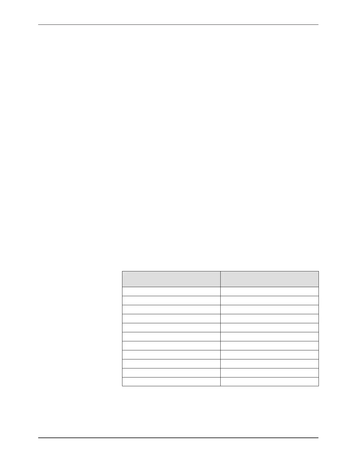
The pressure control setpoints versus the power level output are shown in
Table for the internal blower with VSPD variable speed control enabled.
Table 3-5 Selected Power Level versus Pressure Setpoint
Power Level
(%)
Operating Pressure Setpoint
(inches of water)
100 7
90 6.5
80 5.7
70 5.3
60 4.6
50 4.1
45 3.7
40 3.4
30 3
20 3
Idle 3