Installation
3-8
Part 1089210A04
E 2010 Nordson Corporation
Machine Stop Interlock
CAUTION: Allow only qualified personnel to service the equipment. All
power must be disconnected. Follow the safety instructions in this
document and all other related documentation.
The Machine Stop interlock (Remote I/O pins 15 and 16) can be configured
for Normal or Isolated operation by changing the J1 and J2 jumper positions
on the Remote I/O circuit board.
Jumper Position Pins Description
Normal MSTOP
(15, 16)
Input compatible looking for
contact closure only.
Isolated (ISO) MSTOP
(15, 16)
External 24 Vdc @ 5 mA is
required to maintain interlock
contact closure.
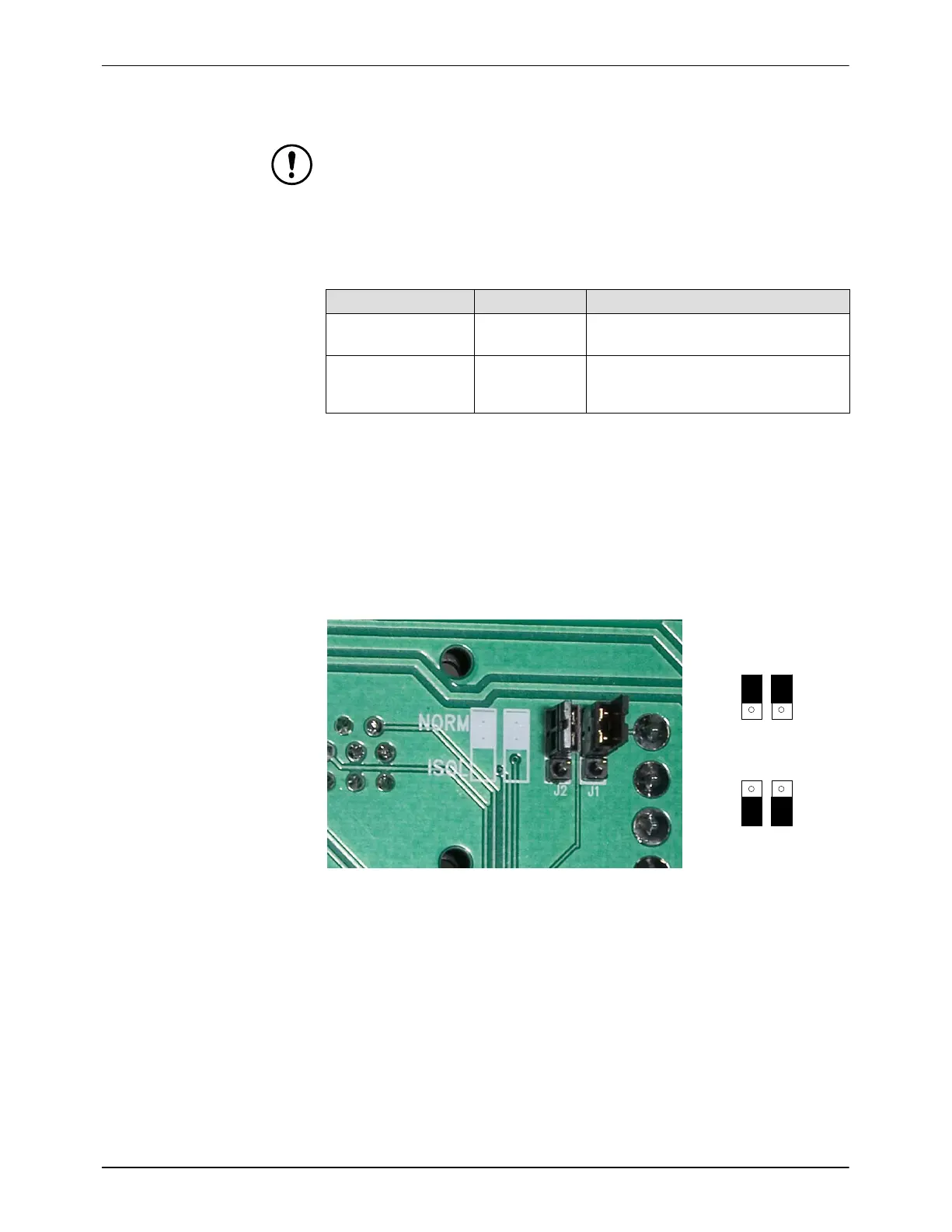
See Figure 3-5. To access the Machine Stop Interlock jumpers remove the
power supply cover. The jumpers are on the back of the I/O connector
circuit board.
S The signal voltage range for the I/O Interlock isolated position is
20−30 volts.
S Both jumpers must be set shown in Figure 3-5.
S Any other jumper combination is invalid and may cause damage.
J2
J1
J2
J1
NORMAL
ISO
Figure 3-5 Machine Stop Interlock Jumper Settings − Shown Set To NORMAL
Remote Power Level Control
The Remote Power Level Control (AIN inputs 4 and 5) function adjusts the
light output based on an external analog signal. This function must be
enabled and configured for 4−20 mA or 0−10 Vdc.
Refer to Table 3-3 and Power Supply Configuration, Table 3-6, for
configuration instructions. Refer to Table 4-4 step 5, in the Operation
section for Power Level setting instructions.