Detector Maintenance Features
$
HQGL[ & $:$&6 $
OLFDWLRQV
AFC-600 Programming PN 51032:A 3/8/99 83
+RZWR,QWHU
UHWD'HWHFWRU6WDWXV'LV
OD
RU0DLQWHQDQFH5H
RUW
Detector Maintenance Status Screens and Detector Maintenance Reports provide the
same information (such as Device Status, Compensation, Peak Value) about a detector.
This section contains descriptions of each item that appears in a Detector Maintenance
Status Screen or a Detector Maintenance Report.
1.
Device Status
The status of the detector: Normal, Alarm, Disable or Test.
2.
Type Code
The software Type Code that identifies the type of detector. Refer to “Type
Codes for Intelligent Detectors” on page 96.
3.
Custom Label
The 20-character user-defined custom label. Refer to “How to Create a
Custom Zone Label (5=
ZONE
)” on page 28.
1RWH
5HIHU WR ´0DLQWHQDQFH
:DUQLQ
V ² 7KUHH /HYHOVµ RQ
D
H IRU GHILQLWLRQV RI
PDLQWHQDQFH OHYHOV
4.
Drift Compensation (Comp:)
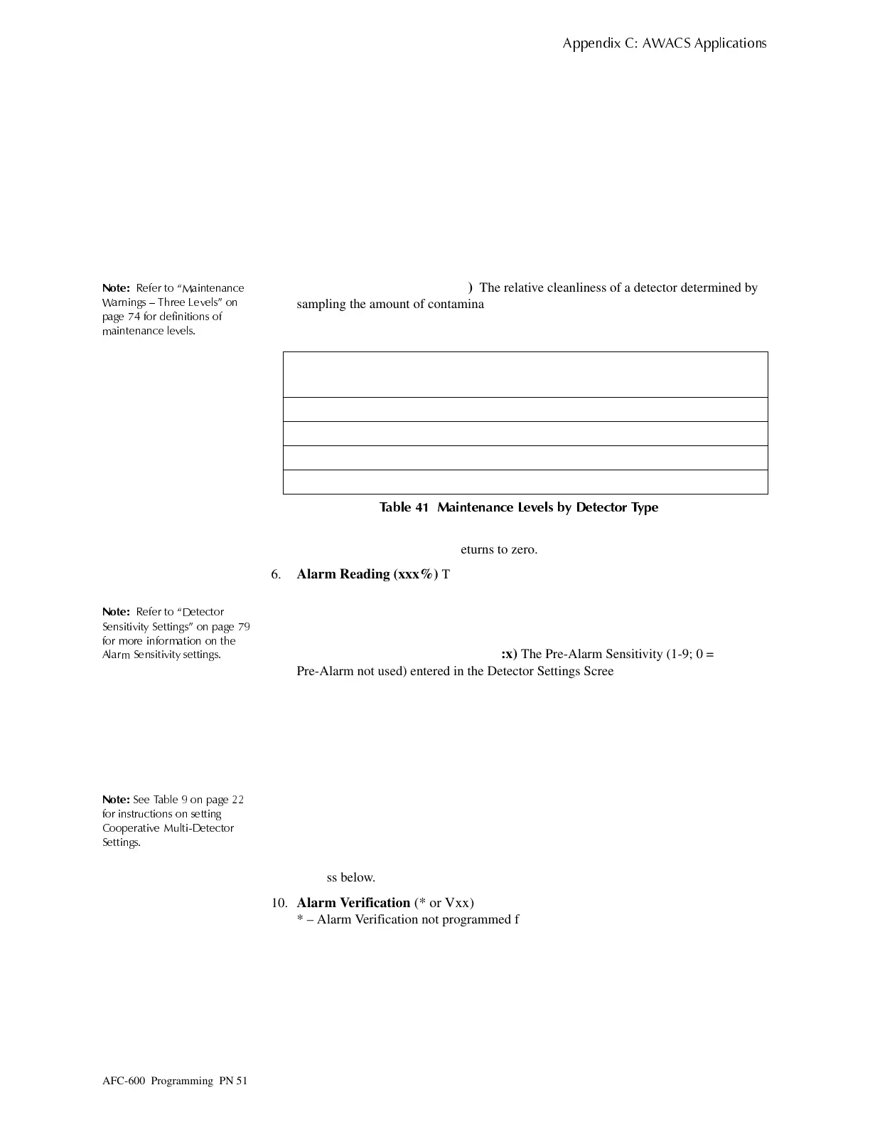
The relative cleanliness of a detector determined by
sampling the amount of contaminants in the detector, ambient air conditions, and the
age of the detector. The Comp value also indicates if a detector requires maintenance.
Table 41 contains a list of the maintenance level values for each type of detector:
7DEOH 0DLQWHQDQFH /HYHOV E\ 'HWHFWRU 7\SH
5.
Peak Value
(0000%)
The highest analog value reached by the detector during the past
week. The peak value slowly returns to zero.
6.
Alarm Reading (xxx%)
The current alarm reading of the detector, as a percentage of
the Alarm Sensitivity setting.
1RWH
5HIHU WR ´'HWHFWRU
6HQVLWLYLW
6HWWLQ
Vµ RQ
D
H
IRU PRUH LQIRUPDWLRQ RQ WKH
$ODUP 6HQVLWLYLW
VHWWLQ
V
7.
Alarm Sensitivity Setting (Ax)
The Alarm Sensitivity (x=1-9) entered in the
Detector Sensitivity Screen (Figure 51).
8.
Pre-Alarm Sensitivity Setting (PA:x)
The Pre-Alarm Sensitivity (1-9; 0 =
Pre-Alarm not used) entered in the Detector Settings Screen (Figure 51). Refer to
“Detector Sensitivity Settings” on page 79 for more information on the Pre-Alarm
sensitivity settings.
9.
Cooperative Multi-Detector Selection
A smoke detector programmed so that it
evaluates readings from nearby detectors in making Alarm or Pre-Alarm decisions.
Cooperative Multi-Detector sensing also allows the combination of ionization with
photoelectric technology in reaching an alarm decision.
1RWH
6HH 7DEOH RQ
D
H
IRU LQVWUXFWLRQV RQ VHWWLQ
&RR
HUDWLYH 0XOWL'HWHFWRU
6HWWLQ
V
* – Multi-not used.
A – combines the detector’s alarm decision with the next address above.
B– combines the detector’s alarm decision with the next address below.
C – combines the detector’s alarm decision with the next address above and the next
address below.
10.
Alarm Verification
(* or Vxx)
* – Alarm Verification not programmed for this detector.
V – Alarm Verification enabled.
xx – Alarm Verification programmed for the detector; xx equals the Verification
Counter (00-99). Refer to Table 9 on page 22 for instructions on setting Alarm
Verification.
11.
Device SLC Address
The SLC address of the detector. Refer to Figure 89 on page 81
for a complete description.
Type of Detector Normal
Low Chamber
Reading
Maint. Alert Maint. Urgent
Ion 006-068 less than 006 92-99 100
Photo 006-069 less than 006 93-99 100
Laser 003-063 less than 003 83-99 100
Multisensor 024-040 less than 024 80-99 100
Technical Manuals Online! - http://www.tech-man.com

 Loading...


