Voice Message Options (VROM and VRAM)
9RLFH $ODUP 6\VWHP
AFP-300/AFP-400 Installation PN 50253:C1 05/22/97 4-35
9RLFH0HVVDJH2SWLRQV9520DQG95$0
2YHUYLHZRI9520DQG95$0
You can install two types of message chips into an AMG-1:
VROM – A nonvolatile memory chip containing a factory-programmed evacuation
message (up to 24 seconds). You can install one or two VROMs into an AMG-1. Refer
to Document 15945 for contents of available VROMs.
VRAM – A programmable memory chip that contains a user-created evacuation
message up to 24 seconds long. Create a message from the AMG-1 microphone or a
cassette tape. You can install one or two VRAMs into an AMG-1.
,QVWDOOLQ
9520DQG95$0
To install the VROM and VRAM chips, follow the steps in Table 4-19 and refer to
Figure 4-41:
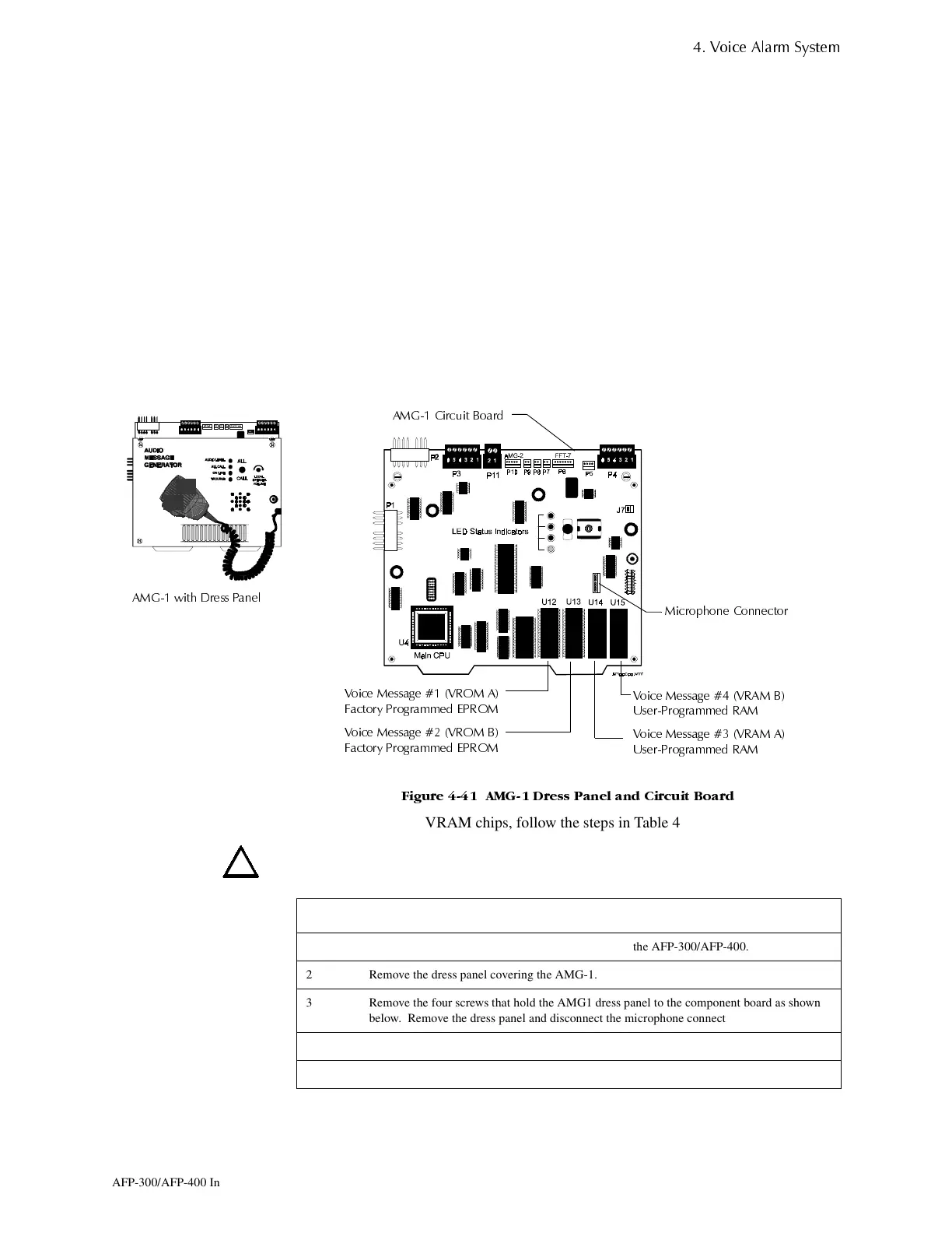
)LJXUH $0* 'UHVV 3DQHO DQG &LUFXLW %RDUG
To install VROM or VRAM chips, follow the steps in Table 4-19.
Caution: Remove AC power at the main service circuit breaker (not the circuit breaker
on the main power supply):
Table 4-19 Installing VROM and VRAM
$0* &LUFXLW %RDUG
9RLFH 0HVVDJH 95$0 %
8VHU3URJUDPPHG 5$0
9RLFH 0HVVDJH 95$0 $
8VHU3URJUDPPHG 5$0
9RLFH 0HVVDJH 9520 $
)DFWRU\ 3URJUDPPHG (3520
9RLFH 0HVVDJH 9520 %
)DFWRU\ 3URJUDPPHG (3520
0LFURSKRQH &RQQHFWRU
$0* ZLWK 'UHVV 3DQHO
Step Action
1 Remove battery power, then remove AC power from the AFP-300/AFP-400.
2 Remove the dress panel covering the AMG-1.
3 Remove the four screws that hold the AMG1 dress panel to the component board as shown
below. Remove the dress panel and disconnect the microphone connector.
4 Install the VROM or VRAM chips in the positions as shown below
To assemble the AMG-1, reverse these instructions.
www.PDF-Zoo.com
 Loading...


