ACT-1 Audio Coupling Transformer
9RLFH $ODUP 6\VWHP
AFP-300/AFP-400 Installation PN 50253:C1 05/22/97 4-37
$&7,QVWDOODWLRQ
,QVWDOODWLRQ 1RWHV
The ACT-1 connects to one of up to eight amplifiers on a channel. Multiple ACT-1s
are required for amplifiers on multiple channels.
To install an ACT-1, follow these steps:
1. Connect the low-level audio circuit to the terminal block on the ACT-1.
2. Connect the ACT-1 to the first amplifier in the chain.
,QVWDOODWLRQ 'LDJUDP
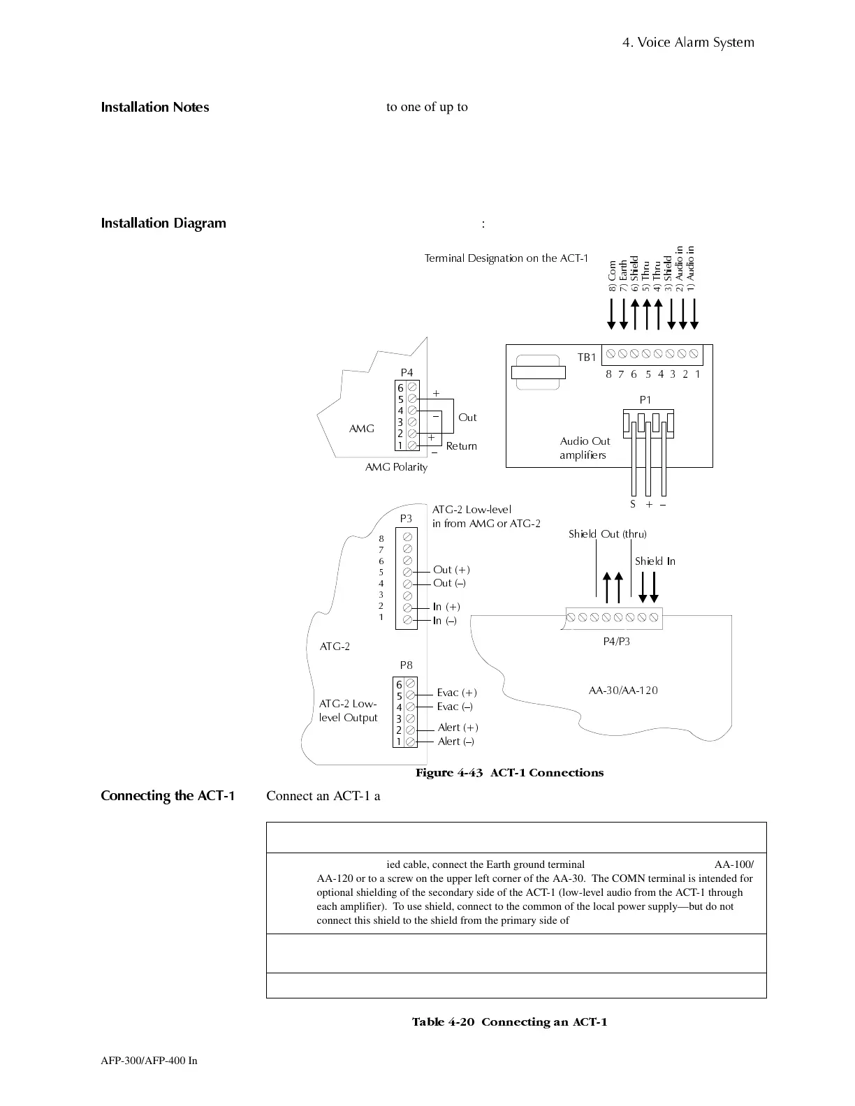
Figure 4-43 shows ACT-1 connections:
)LJXUH $&7 &RQQHFWLRQV
&RQQHFWLQJ WKH $&7
Connect an ACT-1 as follows:
7DEOH &RQQHFWLQJ DQ $&7
7HUPLQDO 'HVLJQDWLRQ RQ WKH $&7
6KLHOG 2XW WKUX
6KLHOG ,Q
3
$$$$
$7*
$XGLR 2XW
DPSOLILHUV
33
$0*
3
3
$7* /RZOHYHO
LQ IURP $0* RU $7*
6²
,Q
,Q ²
2XW
2XW ²
$0* 3RODULW\
2XW
5HWXUQ
$7* /RZ
OHYHO 2XWSXW
$OHUW
$OHUW ²
(YDF
(YDF ²
3
²
²
7%
&RP
(DUWK
6KLHOG
7KUX
7KUX
6KLHOG
$XGLR LQ
$XGLR LQ
Step Action
1 Using the supplied cable, connect the Earth ground terminal on each ACT-1 to P8 on the AA-100/
AA-120 or to a screw on the upper left corner of the AA-30. The COMN terminal is intended for
optional shielding of the secondary side of the ACT-1 (low-level audio from the ACT-1 through
each amplifier). To use shield, connect to the common of the local power supply—but do not
connect this shield to the shield from the primary side of the ACT-1.
2 Daisy-chain the secondary side of the ACT-1 (low-level audio) up to a maximum of eight
amplifiers.
3 Draw additional low level audio risers (isolated from the main riser) from P4 on an audio amplifier.
www.PDF-Zoo.com
 Loading...


