AFP-300/AFP-400 Installation PN 50253:C1 05/22/97 G-1
$SSHQGL[*3RZHU6XSSO\&DOF XODW LRQV
2YHUYLHZ
Follow these guidelines when wiring the AC branch circuit current:
• The control panel requires connection to a separate dedicated AC fire alarm circuit,
which must be labeled “Fire Alarm.”
• The AC power circuit must connect to the line side of the main power feed of the
protected premises.
• Do not power other equipment from the AC fire alarm circuit.
• The AC power circuit wiring must run continuously, without any disconnect
devices, from the AC power source to the control panel.
• Overcurrent protection for this circuit must comply with Article 760 of the
National Electrical Code as well as local codes.
• Use 12 AWG wire with 600-volt insulation for the AC power circuit.
&DOFXODWLQJ$&%UDQFK&LUFXLW&XUUHQW
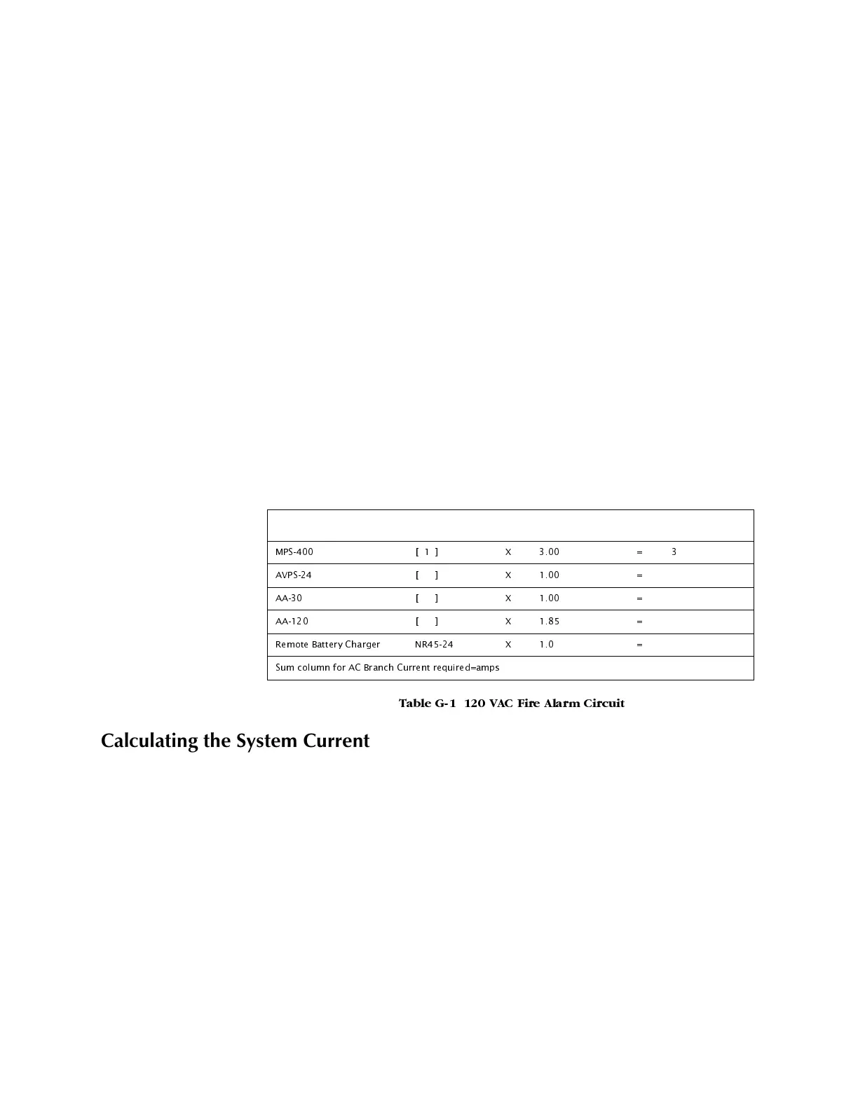
Use Table G-1 to determine the total amount of current, in AC amperes, that a 120 VAC,
50/60 Hz service must be able to supply to the fire alarm system. Devices rated for
240 VAC operation will draw one-half the current listed in Table G-2.
7DEOH * 9$& )LUH $ODUP &LUFXLW
&DOFXODWLQJWK H6\VWHP&XUUHQW'UDZV
The MPS-400 must be able to power all internal system devices (and several external
types of devices) continuously during non-fire alarm conditions. Use column 1 in Table
G-2 to calculate the Non-Fire Alarm Load on the MPS-400 regulator when applying
primary power. The MPS-400 must provide a finite amount of additional current
during a fire alarm condition. Use column 2 in Table G-2 to calculate the additional
current needed during fire alarms. The requirements for non-fire alarm and fire alarm
current loads cannot exceed the capabilities of the MPS-400 listed below:
• 3 A at 24 VDC during Standby; and
• 6 A at 24 VDC during Alarm.
Device Type No. of Devices Current (amps) Total Current
036 > @ ;
$936 > @ ;
$$ > @ ;
$$ > @ ;
5HPRWH %DWWHU\ &KDUJHU 15 ;
6XP FROXPQ IRU $& %UDQFK &XUUHQW UHTXLUHG DPSV
www.PDF-Zoo.com
 Loading...


