,QVWDOODWLRQ
Wiring a Signaling Line Circuit (SLC)
2-42 AFP-300/AFP-400 Installation PN 50253:C1 05/22/97
6/&6KLHOG7HUPLQDWLRQ
2YHUYLHZ
All wiring leaving the control panel must be shielded. Figure 2-56, Figure
2-57, and Figure 2-58 show three methods of wiring termination, depending on the type
of conduit used: a) no-conduit, b) full-conduit, and c) partial-conduit.
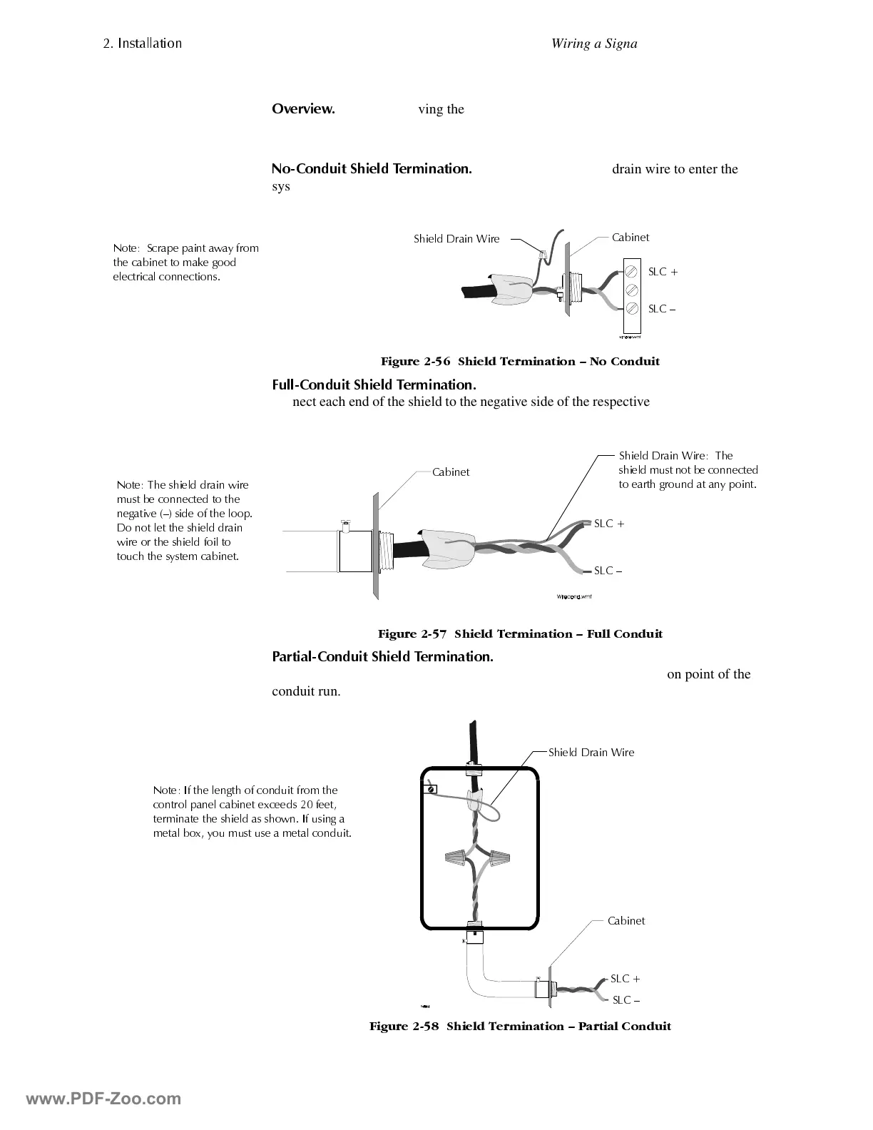
1R&RQGXLW 6KLHOG 7HUPLQ DWLRQ
Do not allow the shield drain wire to enter the
system cabinet. Connect the drain wire to the outside of the cabinet using a cable
connectors as shown in Figure 2-56:
)LJXUH 6KLHOG 7HUPLQDWLRQ ² 1R &RQGXLW
)XOO&RQGXLW 6KLHOG 7HUPLQDWLRQ
For Style 6 or Style 7 field-wiring of the SLC,
connect each end of the shield to the negative side of the respective channel as shown in
Figure 2-57:
)LJXUH 6KLHOG 7HUPLQDWLRQ ² )XOO &RQGXLW
3DUWLDO&RQGXLW 6KLHOG 7HUPLQDWLRQ
Do not allow the shield drain wire to enter the
system cabinet or the conduit. Connect the drain wire to the termination point of the
conduit run.
)LJXUH 6KLHOG 7HUP LQDW LRQ ² 3DUWLDO &RQGXLW
6KLHOG 'UDLQ :LUH
1RWH 6FUDSH SDLQW DZD\ IURP
WKH FDELQHW WR PDNH JRRG
HOHFWULFDO FRQQHFWLRQV
6/&
6/& ²
&DELQHW
6KLHOG 'UDLQ :LUH 7KH
VKLHOG PXVW QRW EH FRQQHFWHG
WR HDUWK JURXQG DW DQ\ SRLQW
&DELQHW
6/&
6/& ²
1RWH 7KH VKLHOG GUDLQ ZLUH
PXVW EH FRQQHFWHG WR WKH
QHJDWLYH ² VLGH RI WKH ORRS
'R QRW OHW WKH VKLHOG GUDLQ
ZLUH RU WKH VKLHOG IRLO WR
WRXFK WKH V\VWHP FDELQHW
6/&
6/& ²
&DELQHW
6KLHOG 'UDLQ :LUH
1RWH ,I WKH OHQJWK RI FRQGXLW IURP WKH
FRQWURO SDQHO FDELQHW H[FHHGV IHHW
WHUPLQDWH WKH VKLHOG DV VKRZQ ,I XVLQJ D
PHWDO ER[ \RX PXVW XVH D PHWDO FRQGXLW
www.PDF-Zoo.com
 Loading...


