IFS-2600 Fire Indicator Panel Section 4 Installation
DOC-01-009 22
Power Supplies NPS-2, NPS-5, NPS-11
AC Operational Voltage
NPS-2 AC 100-240V; 50/60Hz; 1.3A
NPS-5 AC 100-240V; 50/60Hz; 2.5A
NPS-11 AC 100-240V; 50/60Hz; 5A
Output Current @ 27.3V
(Max)
NPS-2 2.6 Amp
NPS-5 5.6 Amp
NPS-11 11.7 Amp
Output Voltage 27.3 VDC
Output Ripple 200 mV
Mains Fail Within 30 seconds of Mains Failure
Charger Fault Below 26.9V or Above 27.7V
Battery Fault
Within 30 seconds of Battery disconnection or when Battery voltage
drops below 24V during a battery test
Battery Test
Automatic. One Hour of quiescent panel load every 6.65± 4 days.
NOTE: The battery fault is latched until a successful battery test is
performed.
Table 4-3, Power Supply Settings
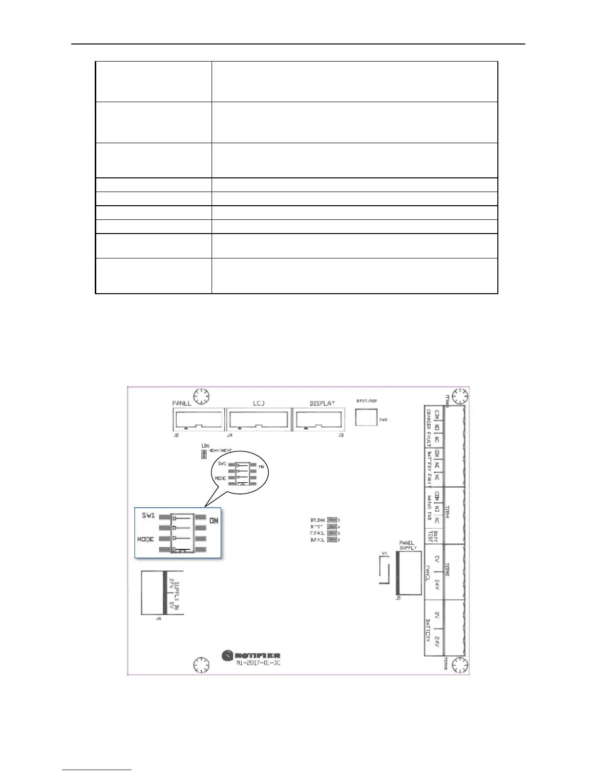
DIP Switch Settings on Power Supply Interface (PSI)
Dip Switches on PSI (NI-2017-01) board SW1.1, SW1.2, SW1.3 & SW1.4 should always be set to OFF
position for automatic mode.
Figure 4-4, DIP Switch settings on PSI