DOC-01-009 62
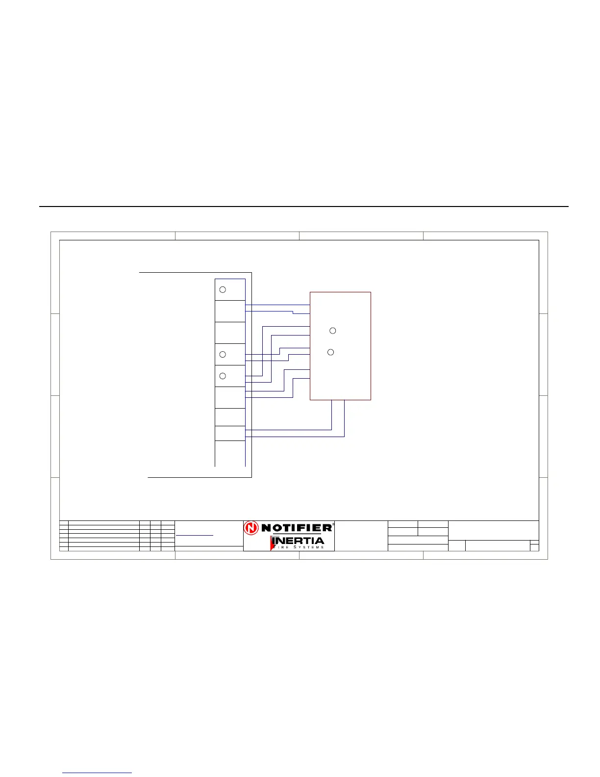
6.4.4. ASE Connection Diagram
1
1
2
2
3
3
4
4
D D
C C
B B
A A
Rev
Size
Drg.
No.
Title
Sheet:
Drawn/
Traced
Engineer
Design
Approved
This Drawingmust not be usedfor Construction
unless signed as approved
7 Columbia Court,
Norwest Business Park
Baulkham Hills NSW 2153
AUSTRALIA
Tel
Fax
Email: support@inertia.com.au
A4
No. Revision - revise on CAD. Do not amend by hand Eng. App. Date
Copyright
This document is& shall
remain the property of
Notifier Inertia FireSystems
Unauthorised useof this
documentin any wayis
prohibited.
Drawing File No.
C
O
61 2 9894 1444
61 2 9899 4156
=DocumentFullPathAndName
Of:
2600
STANDBY
N/C
COM
N/O
BRIGADE 1
COM
BRIGADE 2
N/C
COM
N/O
FAULT
N/O
N/O
N/C
+24
0V
AUX
N
IFS2600
N/C
N/O
AC-FAIL
N/C
COM
N/C
COM
ISOLATE
COM
N/O
ASE CONNECTION
26-ASE
A
1 1
22/8/05 I.P.
ASE
POWER
BRACKET
TYCO #10116
CODE RED #10115
ROMTEK 10117
AC FAIL
BR1
FAULT
ISOLATE
ASE
PCB2004
TERMINATION
N
N
N
N