IFS-2600 Fire Indicator Panel Section 4 Installation
DOC-01-009 33
4.6. Placing Into Operation
Suitably qualified technicians must install the panel. The following check procedures are recommended
after every installation and prior to initial power-up.
A thorough visual inspection should be made to every aspect of the fire panel. This includes loose wire,
metal filings, loose circuit boards, loose cabling, damage in transit etc.
All problems must be rectified immediately as they could cause incorrect operation or permanent damage
to the equipment.
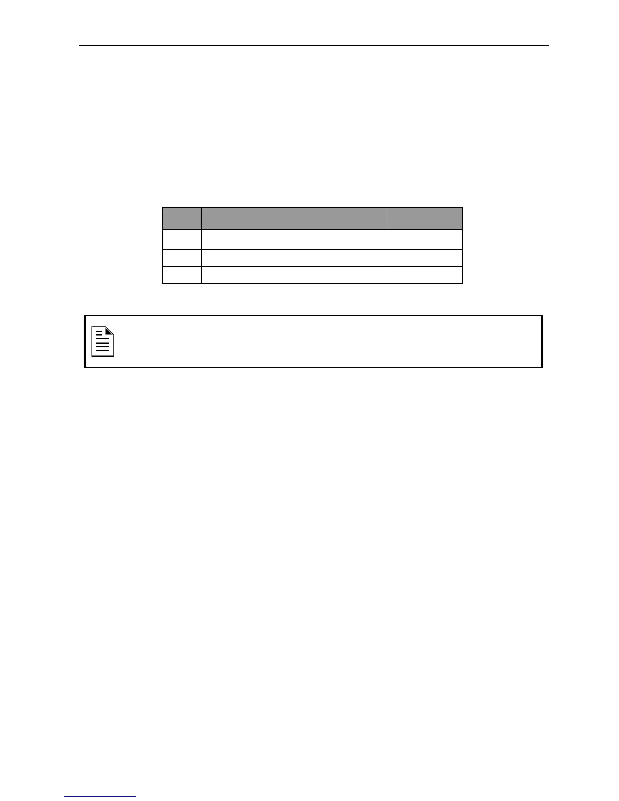
Equipment as Fitted
QTY Description Code
1 MAIN CONTROL BOARD NI-2004-01
1 MAIN TERMINATION BOARD NI-2025-01
1 MAIN POWER SUPPLY INTERFACE NI-2017-01
Table 4-9, Equipment fitted
Initial Checklist
System general appearance good
Cabinet colour and condition good
Cabinet Lock – Can be opened with L003 key
All circuit boards firmly fastened
Manual call point fitted & functional
Viewing window clear and firmly secured
Cable entries adequately sealed
240VAC mains cabling is correctly terminated
All earthing secured
All ribbon cables firmly secured
All operational zones adequately identified
All fuses correct value and fitted properly
All other modules securely fitted
AS 4428 Manufactured & Tested label affixed
You are now ready to power up the IFS-2600 Fire Indicator Panel.
NOTE:
Additional Equipment may depend on required configuration.