DOC-01-009 59
6.4.Technical Drawings
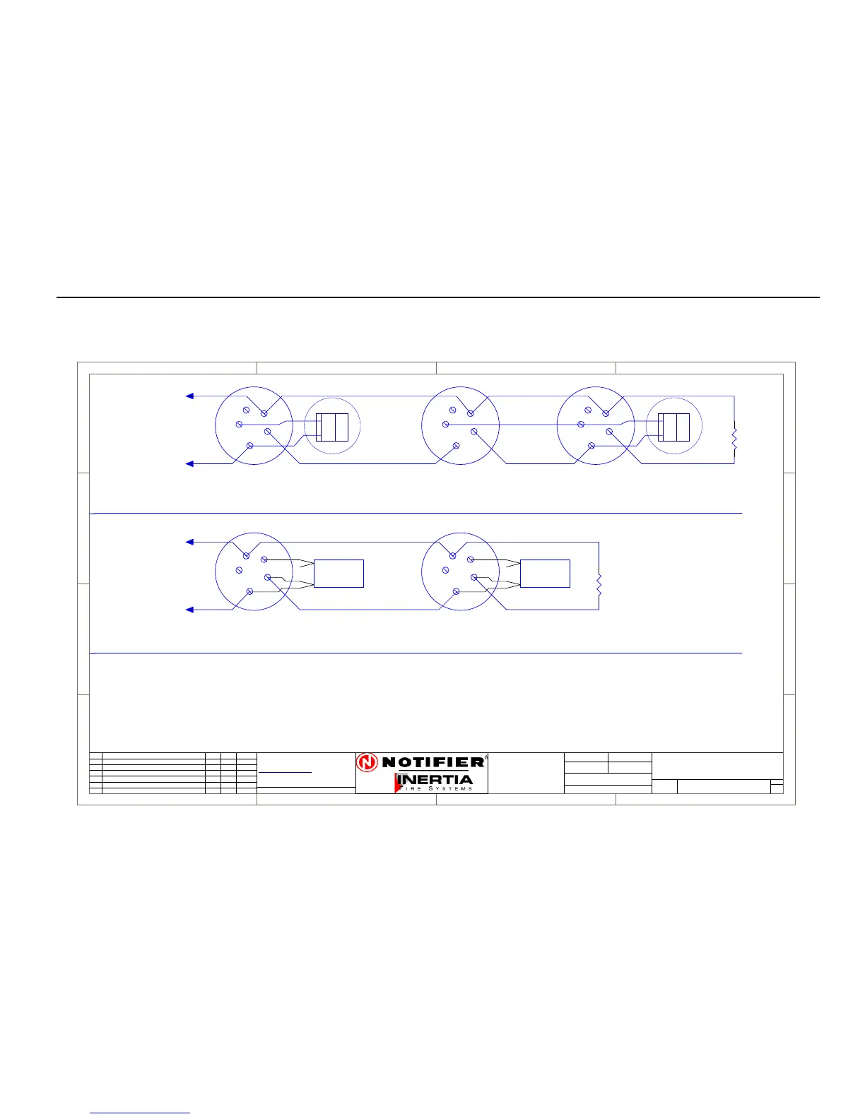
6.4.1. System Sensor Conventional Detector Connection Diagram
1
1
2
2
3
3
4
4
D D
C C
B B
A A
Rev
Size
Drg.
No.
Title
Sheet:
Drawn/
Traced
Engineer
Design
Approved
ThisDrawing must not be used forConstruction
unless signed as approved
7 Columbia Court,
Norwest Business Park
Baulkham Hills NSW 2153
AUSTRALIA
Tel
Fax
Email: support@inertia.com.au
A4
No.
Revision - revise on CAD. Do not amend byhand Eng. App. Date
Copyright
This document is &shall
remain the property of
Notifier InertiaFire Systems
Unauthorised use of this
document in anyway is
prohibited.
Drawing FileNo.
C
O
61 2 9894 1444
61 2 9899 4156
=DocumentFullPathAndName
Of:
+
-
TO PANEL
BASE B401
DET A DET B
-D
+D
+R
RIP
1
2
3
4
5
1
2
3
4
5
EOL
4K7
+
-
TO PANEL
EOL
4K7
DET B
-D
+D
+R
RIP
1
2
3
4
5
BASE B401R
1
2
3
4
5
BASE B401R
BASE B
1
2
3
4
5
PROBE
SEALED
PROBE
SEALED
PROBE B
BASE A
PROBE A
SEALED DETECTOR CONNECTION DIAGRAM
CONVENTIONAL DETECTOR CONNECTION DIAGRAM
+R
+D
-D
470R
+R
+D
-D
Not current limited (3-24 V)
Current limited 10 mA
Common Return
BASE B401
REMOTE INDICATOR
SS-DET
A
SYSTEM SENSOR
CONVENTIONAL DETECTOR
CONNECTION DIAGRAM
1 1
I PERRY I PERRY
I PERRY
( NORMAL HEAD NOT CONNECTED )
+
-
TOPANEL
BASEB401
DETA DETB
-D
+D
+R
RIP
1
2
3
4
5
1
2
3
4
5
EOL
4K7
+
-
TOPANEL
EOL
4K7
DETB
-D
+D
+R
RIP
1
2
3
4
5
BASEB401R
1
2
3
4
5
BASEB401R
BASEB
1
2
3
4
5
PROBE
SEALED
PROBE
SEALED
PROBEB
BASEA
PROBEA
SEALEDDETECTORCONNECTIONDIAGRAM
CONVENTIONALDETECTORCONNECTIONDIAGRAM
BASEB401
(NORMALHEADNOTCONNECTED)