IFS-2600 Fire Indicator Panel Section 4 Installation
DOC-01-009 23
4.4.2. Power Supply Ratings & Settings for IFS-2005 & IFS-2006 Boards
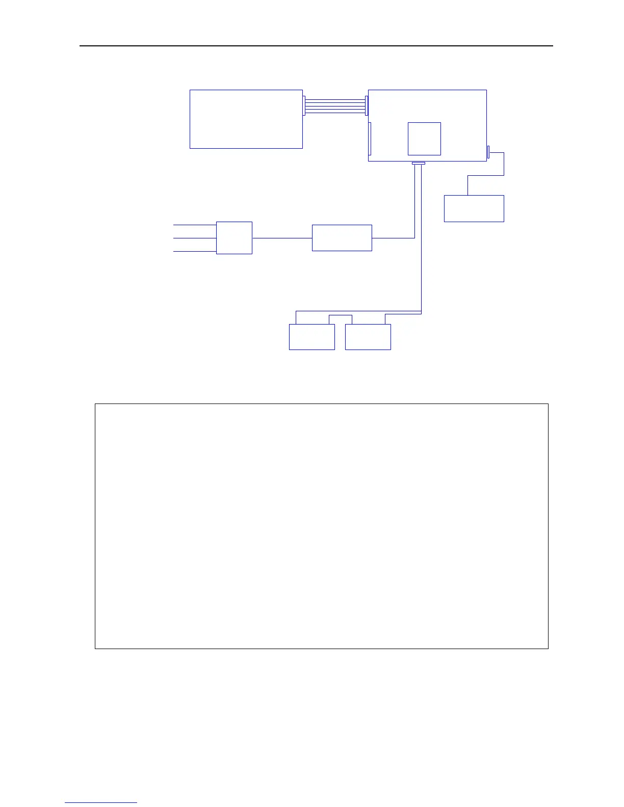
Figure 4-5, Power Supply Schematics (IFS-2004, IFS-2005 & IFS-2006 Boards)
IFS -2005
12VBATTERY 12V BATTERY
+ +
-
-
MAINPROCESSORBOARD
MAINTERMINATIONBOARD
240V/30VAC
100VA
TRANSFORMER
2600/DHTX
100VA
TRANSFORMER
240V
ISOL
S/W
MAINS SUPPLY
240V AC
IFS -2004
POWER
IFS - 2006
ZONEDISPLAYS1-8
PANEL
POWER
D/HOLDER
POWER
OPTION
SUPPLY
BOARD
ACTIVE
NEUTRAL
EARTH
Important Note:
After a power failure, the battery will only reconnect to the charger if the battery voltage is above
approximately 20V ± 2V.
A battery fault will be generated in the event that the battery does not automatically reconnect. This is to
ensure that a faulty or dead flat battery (due to an extended power failure) does not bring the entire
system down.
In order to reconnect a flat battery, it is necessary to disconnect the battery from the panel and charge it
externally. The battery should be thoroughly tested before returning it to service.
In the event that an external charger is not available, the battery may be trickle charged above 22V via a
30 ohm, 5W resistor connected between the 24v Aux Output and the battery positive terminal. A 1N4004
battery from pulling down the main panel voltage. Trickle charging the battery by this method may take
several hours to bring it up to the minimum level.
The battery can then be reconnected to the panel for charging via the internal battery charger. It is
important that the voltage on the battery be monitored to ensure that it is charging. The battery should
then be left for 24 hours and then fully tested to ensure that no damage has occurred due to the deep
discharge.