CHAPTER 3 - MAINTENANCE / REPAIR PROCEDURES
Ohaus Corporation www.ohaus.com 36 Explorer
®
Series Service Manual
Re-Assembly:
Reverse the disassembly procedure to assemble the balance. Ensure that there is no foreign
material between the Base mounting surfaces and the Load cell.
Take special care to route the wires and cables according to their original positions. Proper routing
is important for RFI/ESD performance. Ensure that the wires or cables are not pinched during re-
assembly.
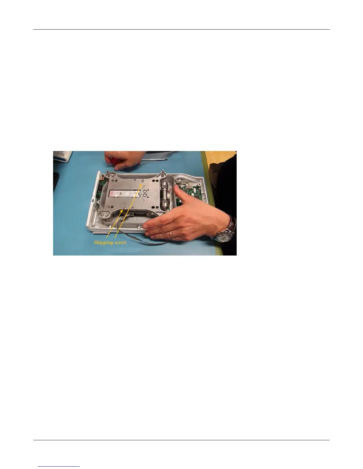
3.5 REMOVING LOAD CELL PROTECTION SCREWS
Attention: This process is only needed for 1, 2 and 3 decimal scales.
It is very important to remove the shipping protection screws after assembling the load cell into the
scale housing; otherwise the load cell will not work. Please follow the steps below.
1. Place the load cell in front of you, as shown in the picture below.
2. Start by removing the screw on your left side. Please pay attention to not shift the spider from its
position during this procedure. Follow by removing the screw on the right side.
3. Remove both screws with shims completely from the load cell. Please store the screws and
shims in a safe place.