CHAPTER 3 - MAINTENANCE PROCEDURES
Explorer
®
Series Service Manual 39 Ohaus Corporation www.ohaus.com
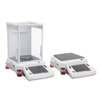
3.2.6 Base
1. Open the Base Module – see Section 3.2.
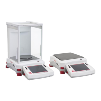
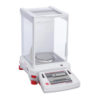
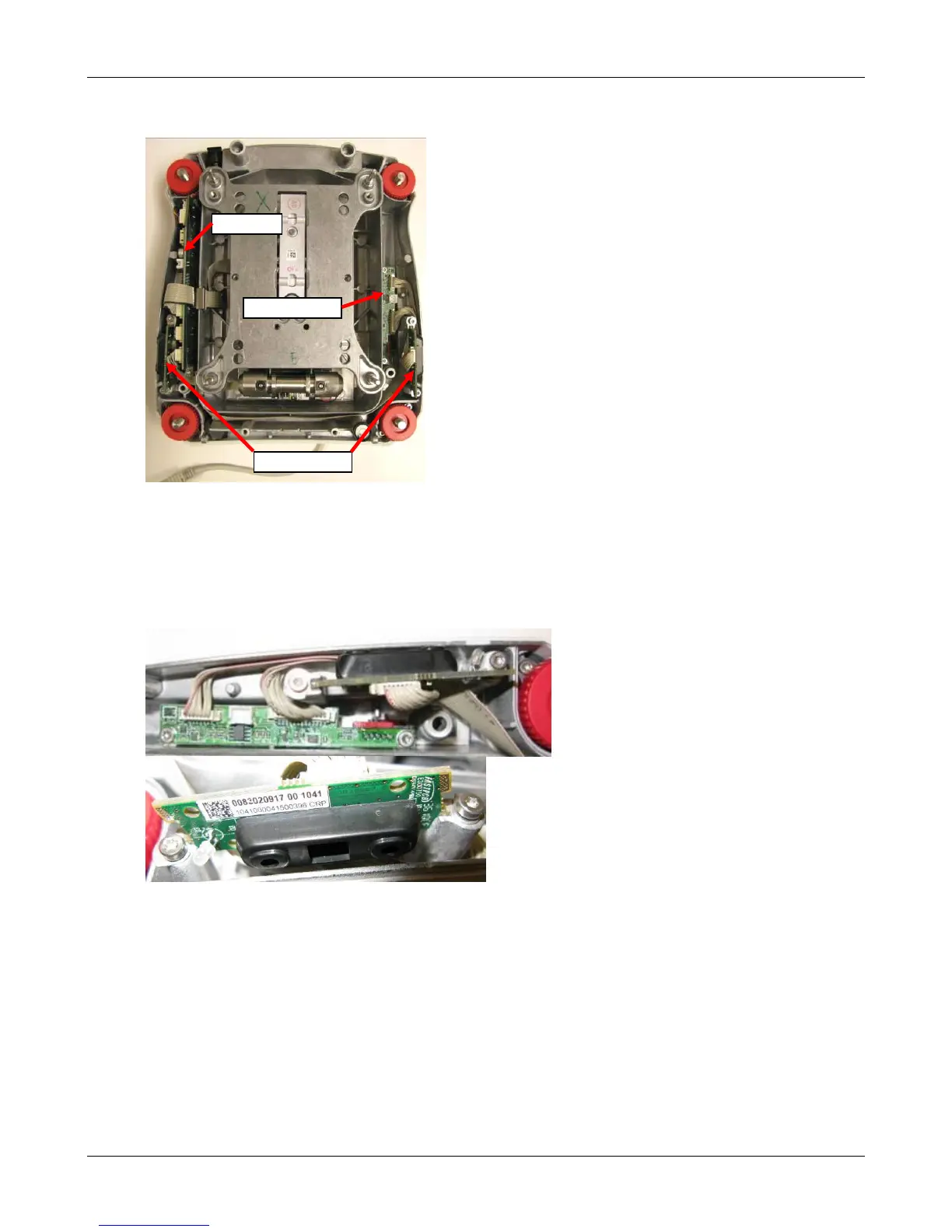
2. Remove IR Sensor PCBAs
The left and right PCBAs are identical. The PCB is symmetrical about its length so that the
Indicator LED is able to be mounted forwards on both sides. The cable connector will face up
or down depending on the side it is mounted.
• Loosen the 2 retaining screws approximately 2 turns
• Rotate the retaining washers so that it no longer engages the PCB, slide out the PCBA
• Disconnect the cable at the Connect PCBA.