CHAPTER 3 - MAINTENANCE / REPAIR PROCEDURES
Ohaus Corporation www.ohaus.com 40 Explorer
®
Series Service Manual
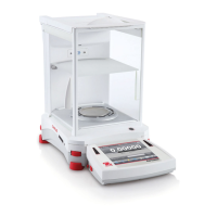
3. Remove the Connect PCBA
• Disconnect the Connect Cable to the Main PCBA.
• Remove the 2 retaining screws, the PCB is now free
• During disassembly and re-assembly note how the switch engages the Switch
Actuator.
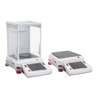
4. Remove Main PCB
Note: For EX12001, EX24001 and EX35001 models please see section 5.
• Remove the left IR Sensor PCBA (see above).
• Disconnect the cables along the top edge of the PCB.
• Loosen the 2 retaining screws approximately 2 turns
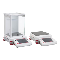
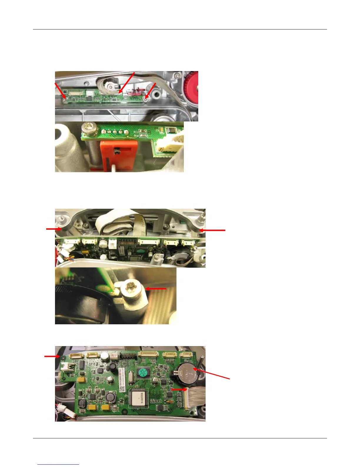
• Rotate the retaining washers so that it no longer engages the PCB, slide out the PCB
• Disconnect the Power Jack and the Ribbon Cable to the Connector PCBA cables