Oki Data CONFIDENTIAL
42930511TH Rev. 2 188 /
S100
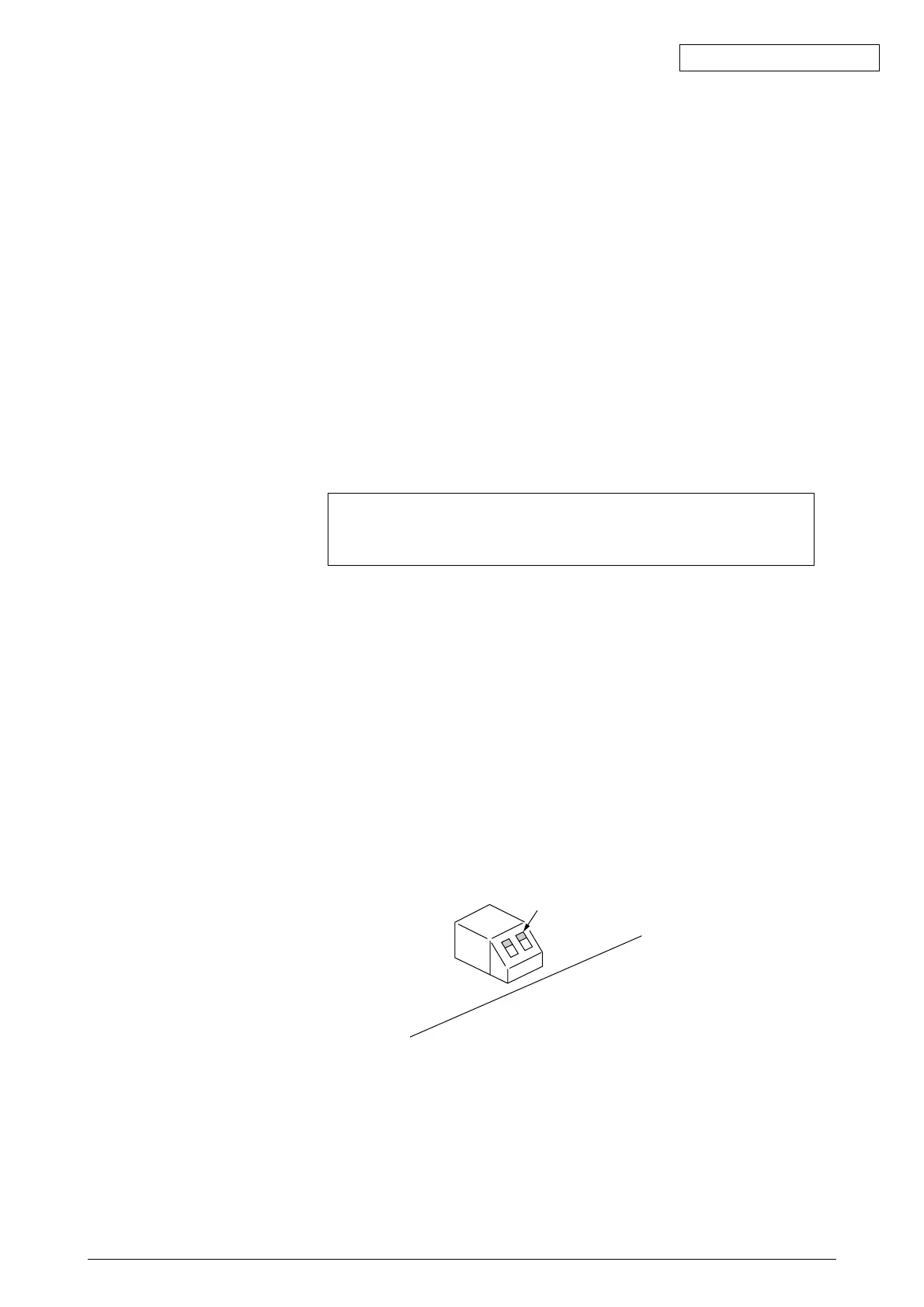
Both switches are facing upward.
ASP PCB Download Switch Location
*1 ASP PCB for 1200dpi Analysis Reference
When “Communications Error” appears on the display panel, this message is displayed with the
PU. This indicates a problem has occurred in the ASP board during its initialization. In such a
case, open the sheet metal of the CU board and check the lit LED on the ASP board to locate
the problem.
The LED mounted on the ASP PCB come in the following types. The description of the cases
when they do not light up normally are described below.
PWR_GOOD (Green): This indicates the power status of the ASP PCB. It lights up when the
various power output sources (CPU core voltage, 2.5V, 3.3V, 5V0 of the
ASP PCB are normal. If it does not light up, disassemble the BYN PCB
(optional), HMK PCB, RAM_DIMM and HDD. Check to see if it will
lightup in this state.
DIAG_LED[3: 0] (Red): This indicates the initialization processing state of the ASP PCB. It will
all lightup immediately after the power is turned ON. It will all dim down
when the initialization process is successfully completed. If all lights do
not dim, then there is a CU PCB malfunction. If all lights do not dim,
then disassemble the BYN PCB (optional), HMK PCB, RAM_DIMM and
HDD. Check to see if it will lightup again in this state.
HDD_LED (Red): This lights up when accessing the HDD. If it does not start flashing even
after the power is turned ON, replace the HDD and check to see if the
problem is corrected. Check to see that the download switch is facing
upward.
CF_LED (Red): This lights up when accessing the CompactFlash. The CompactFlash
is used with only some domestic models. If it does not start flashing even
after the power is turned ON, replace the CompactFlash and check to
see if the problem is corrected. Check to see that the download switch
is facing upward.
FPGA_LED (Green): This lights up when communication is enabled between the engine and
panel interface. If it does not lightup, then disassemble the BYN PCB
(optional), HMK PCB, RAM_DIMM and HDD. Check to see if it will
lightup again in this state.
* When the HDD is not correctly recognized or when the download
switch is in the down position, DIAG_LEDs 2 and 0 are on and
DIAG_LED 1 is out.