EasyManuals Logo

Oki LD670 User Manual

Oki LD670
224 pages
To Next Page IconTo Next Page
To Previous Page IconTo Previous Page
Page #191 background imageLoading...
Page #191 background image
190
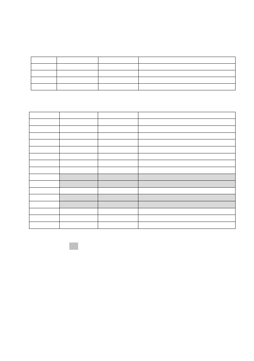
12-2. Dual Interface
(1) Type B Connector: 4 Pin
Pin No.
Signal name
I/O direction
Signal line name
1
N.C
---
2
D-inB
Input/Output
D-
3
D+inB
Input/Output
D+
4
SG1
---
Ground
(2) Serial interface connector
Pin No.
Signal name
I/O direction
Function
1
FG
---
Frame ground
2
TXD
Output
Send data
3
RXD
Input
Receive data
4
RTS
Output
Send request
5
CTS
Input
Send permission
6
DSR
Input
Data set ready
7
SG
---
Signal ground
8 to 12
N.C.
---
Unused
13
SG2
Input
+24 V ground
14
SG2
Input
+24 V ground
15 to 17
N.C.
---
Unused
18
+24V
Input
Power supply for mechanism drive
19
+24V
Input
Power supply for mechanism drive
20
DTR
Output
Data terminal ready
21 to 24
N.C.
---
Unused
25
INIT
Input
Forced reset
Notes 1: To supply power from the power connector, do not connect the pins
shaded ( ) in the above table.
Notes 2: Use inch- screws to secure the connection.
Notes 3: Shielded USB cables must be used.

Table of Contents

Other manuals for Oki LD670

Questions and Answers:

Question and Answer IconNeed help?

Do you have a question about the Oki LD670 and is the answer not in the manual?

Oki LD670 Specifications

General IconGeneral
BrandOki
ModelLD670
CategoryLabel Maker
LanguageEnglish

Related product manuals