3 – 9
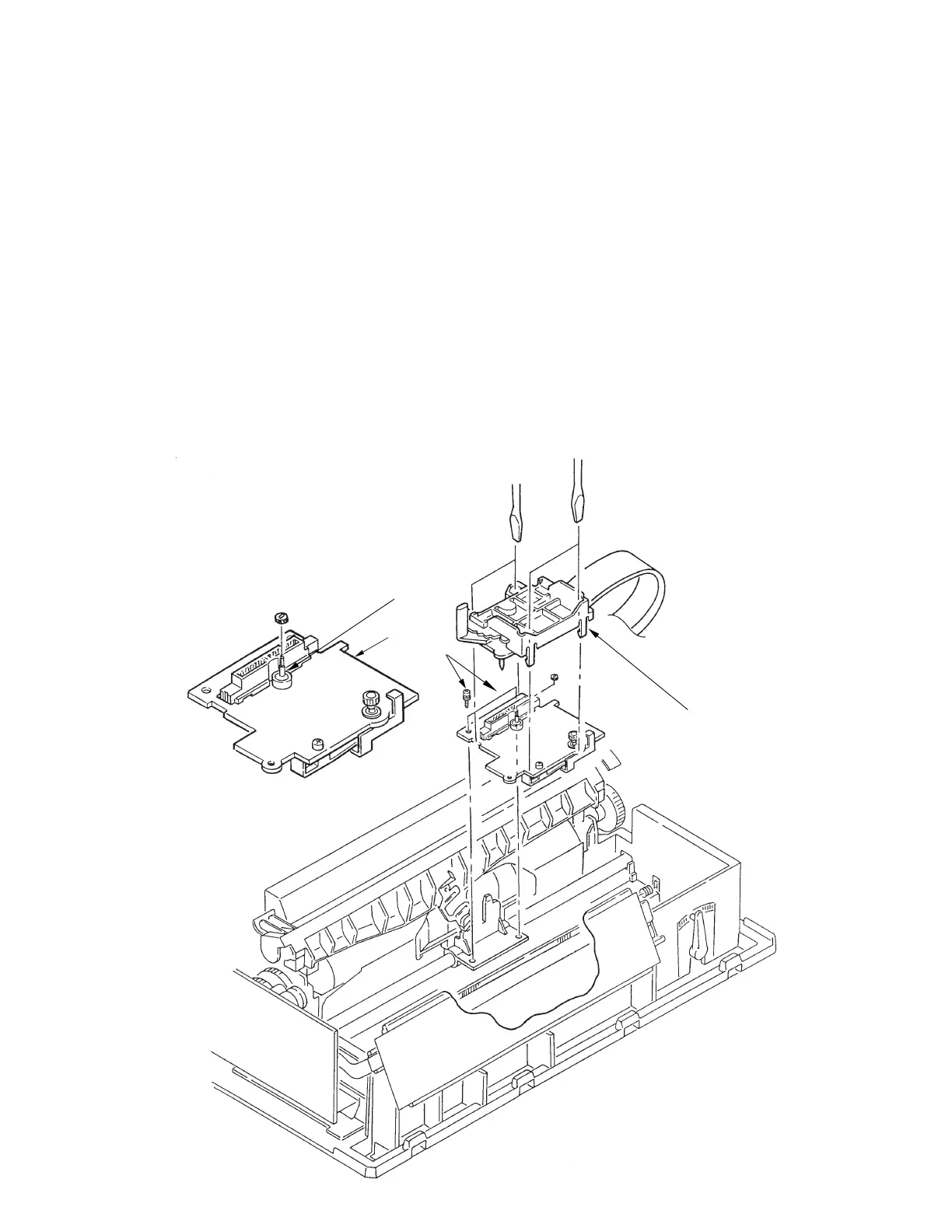
3.3.5 Gear Case Assy
(1) Remove the printhead (see 3.31).
(2) Remove the shim from the cariage frame.
(3) Remove the upper cover (see 3.3.4).
(4) Move the carriage Assy to right side, remove two screws 1, then remove the carriage Assy.
(5) Disengage claws on the gear Assy (4 places).
Using a flat-blade screwdriver, push to widen the claw for easy disengagement.
(6) Lift up the gear case Assy 3 and release the carriage cable from the cable clamp of the
gear case Assy.
(7) To install, follow the removal steps in reverse order. Be sure to replace the shim on the
carriage frame in exactly the same position as it was before disassembly
Notes on installation:
(1) To assemble, align the direction of the SP motor axis 4 with the Gear Hole of the Gear
Case assy.
(2) Be sure to check and adjust the gap between platen and printhead (see 4-1).
2
4
3
1