3 – 14
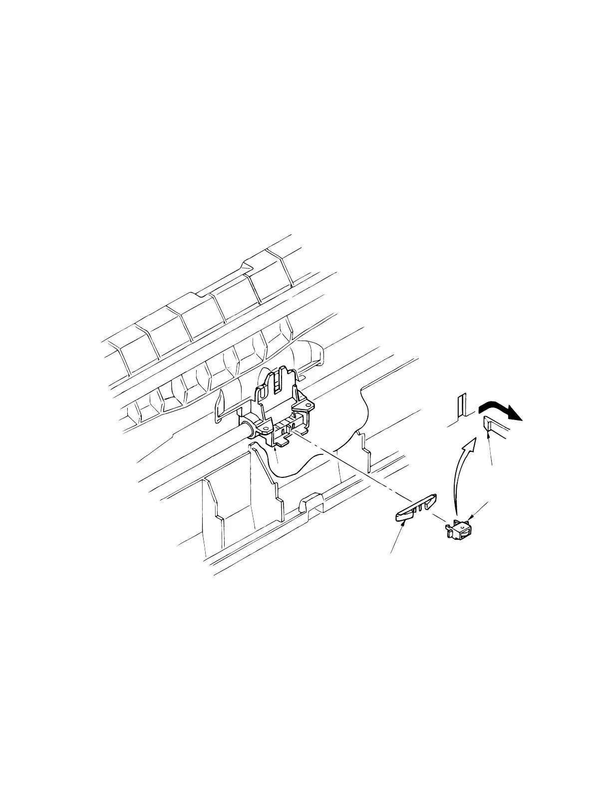
3.3.10 Backup Roller Holder Assy
(1) Remove the upper cover (see 3.3.4).
(2) Remove the printhead (see 3.3.1).
(3) Remove the carriage Assy (see 3.3.5 (3)).
(4) Remove the backup roller spring 2.
Disengage claws of roller holder from the carriage frame 1 (2 places), and remove the
backup roller holder assy 3.
(6) To install, follow the removal steps in reverse order.
Note: Small round hole with metal tip on back of roller holder assy 3 should be facing
up when installing.
Claw (2 places)
1
3
2