3 – 19
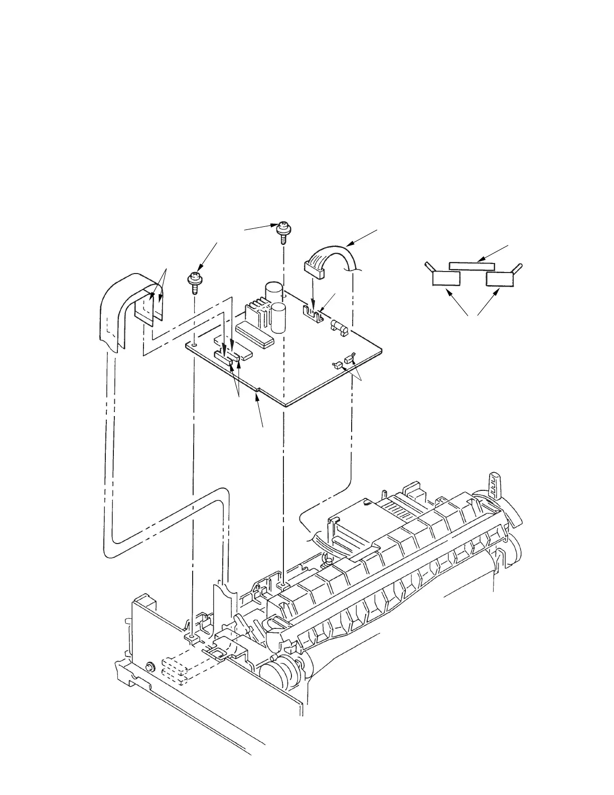
3.3.15 Control/Power Supply Board (SDCT)
(1) Remove the upper cover (see 3.3.4).
(2) Disconnect the two flexible cables 3 from connector 2 on the Control/Power Supply Board
1.
(3) Remove cable 5 from connector 4 on the control/power supply board 1.
(4) Remove the two screws 6, and remove the controlpower supply board 1.
(5) To install, follow the removal steps in reverse order.
Note on installation:
To install the control/power supply board, set the change lever to the top position so that
the switch lever 7 will not catch on the microswitches 8.
3
6
5
7
8
4
8
1
2