3 – 24
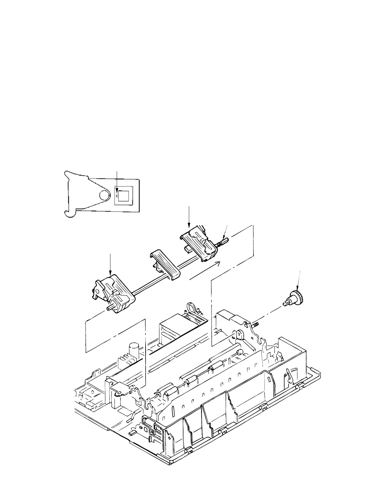
3.3.20 Rear Tractor Assy
(1) Remove the printhead (see 3.3.1).
(2) Remove the ribbon protector (see 3.3.2).
(3) Remove the pull-up roller assy (see 3.3.3)
(4) Remove the upper cover (see 3.3.4).
(5) Remove the reset spring (see 3.3.17 (3))
(6) Remove the tractor gear 1.
(7) Shift the drive shaft 2 to the right side to remove (in the direction of the arrow).
(8) To install, reverse the removal procedure.
Note on installation:
When the tractor assemblies (L) 3 (R) 4 have been detached from the drive shaft, align
the protrusions 5 of the pin tractor wheels in the same direction as before assembly.
5
1
2
3
4