DMTA041-01EN [U8778479], Rev. C, May 2014
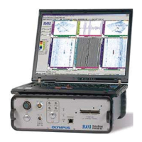
Instrument Overview
17
When this indicator light is off, it indicates that the conventional ultrasound mode
is disabled.
The 15 V to 24 V requirement is the voltage needed at the DC IN connector site. The
length of the cable has an impact on the power supply’s nominal value. For example,
with a nominal value of 15 V and 30 meters of cable, the voltage at the connector site
could be lower than 14 V, which is too low for the instrument to start up.
P125, P126, P127, P128
These LEMO connectors enable the unit to be used with conventional ultrasound
probes. The
P connectors correspond to the last four channels of the UT PHASED
ARRAY connector.
When the instrument is used in conventional ultrasound mode with the P125, P126,
P127, and P128 connectors, the voltage present on the P connectors can be dangerous
and create a shock hazard.
AC
The letters AC stand for alternating current.
When this indicator light is green, it indicates that the unit is powered by
alternating current through the power entry module.
When this indicator light is red, it indicates that, either the internal AC power
supply is below or over the 100 VAC to 240 VAC range ±10 %, or that the
instrument is defective and requires servicing. If the input voltage is found to be
within limits, see “Technical Support” on page 11.
DC
The letters DC stand for direct current.
When this indicator light is green, it indicates that the unit is powered by direct
current through the
DC IN connector.
When this indicator light is red, it indicates that either the DC power supply is
below or over the 15 ±1 VDC to 24 ±1.5 VDC range, or that the instrument is