CP TD1 Reference Manual V 1.44
152
In most cases, the tap changer consists of two units. The first unit is the tap
selector, which is directly located inside the transformer tank and switches to the
next higher or lower tap without carrying current. The second unit is the diverter
switch, which switches without any interruption from one tap to the next while
carrying load current. The commutation resistances R limit the short circuit
current between the taps which could otherwise become very high due to the
interruption-free switching of the contacts. The switching process between two
taps takes approximately 40 - 80 ms.
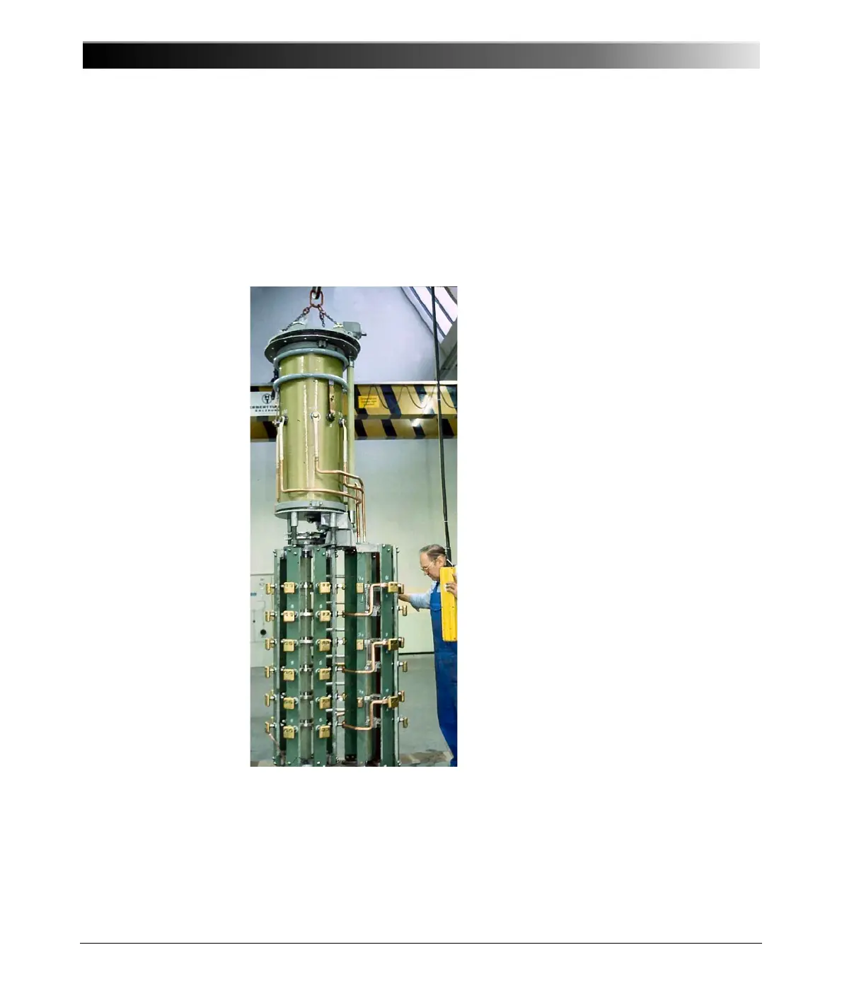
Figure 12-10 Tap changer
Figure 12-10 shows a tap changer with the tap selector (lower part) and the
diverter switch (upper part). In Figure 12-11, a transformer with an attached tap
changer is shown. In both pictures the separate oil tank of the diverter switch is
clearly visible.

 Loading...


