OMICRON 49
Power transformers
For the measurement of C
T
the HV output has to be attached to the TV winding. The other windings are
connected to IN A and IN B. This way, also C
LT
and C
HT
could be measured (see Figure 5-10 and Table
5-6 below).
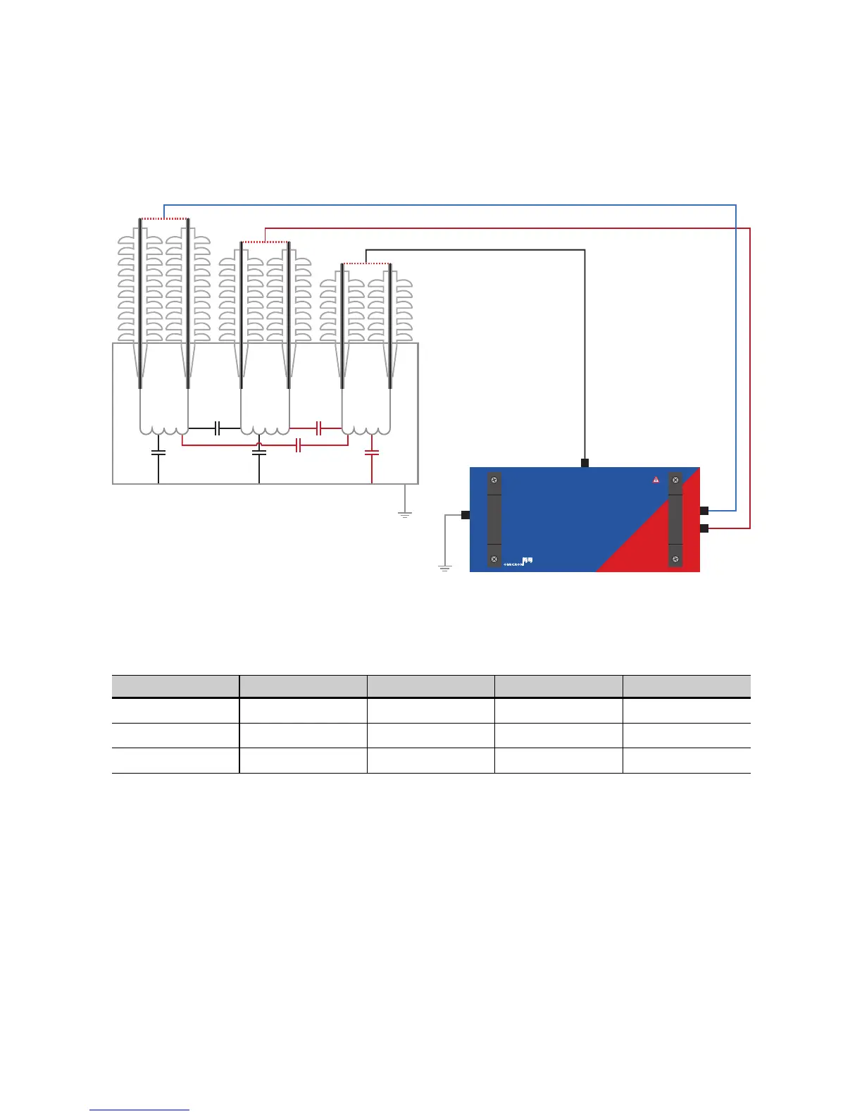
Figure 5-11: CP TD1 connected to a three-winding transformer for the measurement of C
T
With this setup the following 3 configurations are available:
Table 5-7: Modes available with a measurement setup as seen in Figure 5-11
Mode IN A IN B Ground Result
GSTg-(A+B) Guarded Guarded Measured C
T
UST-A Measured Guarded Guarded C
LT
UST-B Guarded Measured Guarded C
HT

 Loading...


