OMICRON 55
Power transformers
Figure 5-20 shows the results for 10 kV:
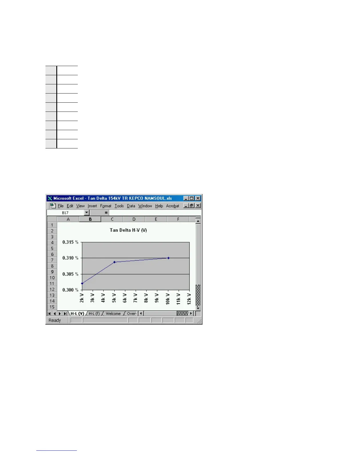
A voltage scan measurement is shown in Figure 5-21, a frequency scan in Figure 5-22.
Voltage and frequency scans enable additional information about the insulation quality. They should be
saved as "fingerprint" for future measurements. For all the described measurements only three different
connections of the test leads are necessary. Preparing the test in the office by utilizing the CPC Editor,
the testing time on-site can be reduced to a minimum.
Figure 5-21: Voltage-scan for H-L (V) (50 Hz)
1 H+HL In line 4, the difference of the capacity values of test 1 - test 2 is calculated so it can
be compared to test 3. In lines 8 and 12, the differences of lines 5-6 and 9-10 are
calculated to also enable a comparison to tests 7 and 11. This way the reliability of
the measured values can be checked. For the tertiary winding, the test voltage was
reduced to 5 kV due to the lower rated voltage of this winding.
2H
3HL
5L+LT
6L
7LT
9T+TH
10 T
11 TH

 Loading...


