When the Drive Programming program is stopped, the status before the program stop is
retained for multi-function outputs controlled by the Drive Programming.
For this reason, configure the system so that the stop of the Drive Programming program in the
inverter can be detected by the Drive Programming start signal and the alarm (trip) signal, and
the inverter's peripheral devices can be stopped safely.
• When the Drive Programming program is stopped, the data of the output terminal variables
before the program stop is retained. When the program execution is started again, the pro-
cess begins with the retained data.
However, the outputs with MO1 to MO7 (General-purpose output) not set for the Drive
Programming are controlled as the inverter's multi-function outputs independently of the
program.
• If multiple tasks use the same multi-function terminal, the output status of the task which is
executed last will be effective. Considering safe control, we recommend you to avoid using
multiple tasks for control.
• Even if you select MO1 to MO7 (General-purpose output 1 to 7) for the Multi-function Output
Selection (11 to 13) or for the Multi-function Relay Output (RY) Function Selection, you can
select NO (NO contact) or NC (NC contact) for the Multi-function Output Operation Selection
(C031 and C033) or for the Multi-function Relay Output (RY) Operation Selection (C036).
You can use the inverter's frequency reference input (analog voltage input) O terminal, the frequency
reference input (analog current input) OI terminal and the
frequency reference auxiliary input (analog volt-
age input) O2 terminal
as the analog input terminal variables XA(0) to XA(2) of the Drive Programming
function.
You can continuously monitor the status of the analog inputs regardless of the parameter settings.
• The analog input terminal variables XA(0) and XA(1) are unsigned 1-word variables, and XA(2) is a
signed 1-word variable. This variable is read-only.
• The variables are displayed in increments of 0.01% as a percentage of the maximum analog input
10 V or 20 mA.
• To adjust the analog inputs, use the following inverter parameters: (O: A150 to A154, OI: A155 to
A159, and O2: A160 to A163).
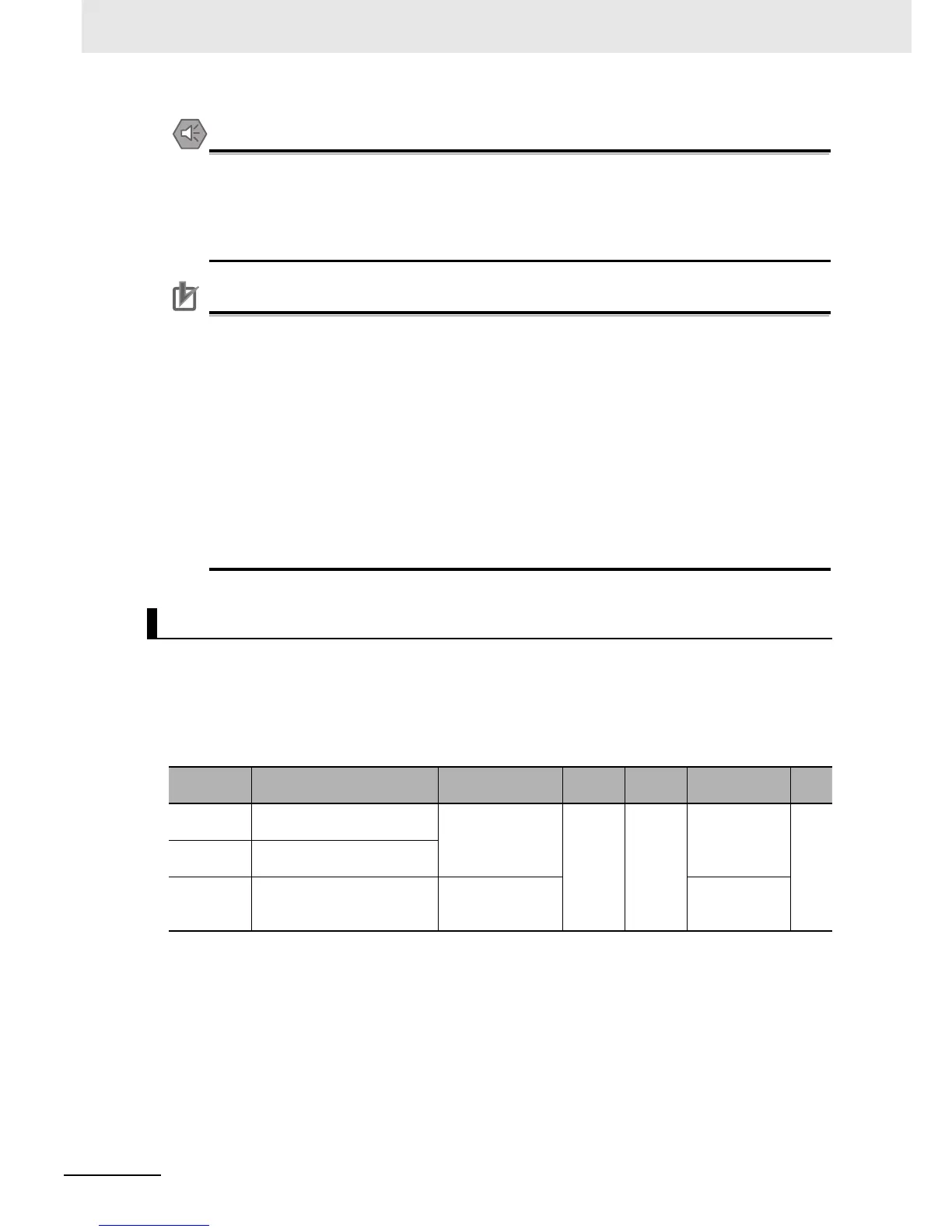
Analog Input Terminal Variables XA(0) to XA(2)
Function
variable
Description Data range
Default
data
Unit Data size R/W
XA(0) Analog input terminal variable
(O terminal: 0 to 10 V input)
0 to 10,000 0 0.01% Unsigned
1 word
R
XA(1) Analog input terminal variable
(OI terminal: 4 to 20 mA input)
XA(2) Analog input terminal variable
(O2 terminal: -10 to 10 V
input)
10,000 to 10,000 Signed
1 word
 Loading...


