2 Specifications
2 - 2
Drive Programming User’s Manual (I580-E2)
2-1 Specifications
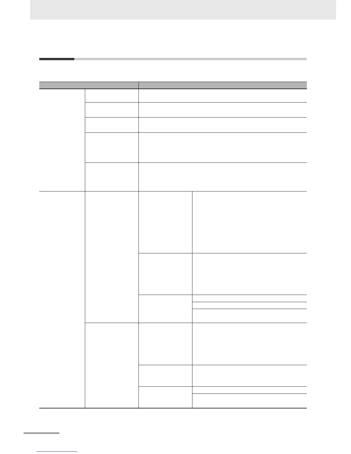
The following table shows the specifications related to the Drive Programming.
Item Specifications
Program specifica-
tions
Programming lan-
guage
Flowchart and text language method
Input device Windows personal computer
(OS: Windows XP-SP3, Windows Vista, or Windows 7)
Program capacity 1,024 steps max.: 6 KB
(1,024 steps max. for a total of 5 tasks)
Programming support
function
Functions supported in Inverter/Servo support tool CX-Drive
• Program editing and display
• Program compilation (Program syntax check)
• Program downloading, uploading, and all clear
Execution format • Execution by interpreter
• Execution cycle: 2 ms/step (5 commands executable through 5-task paral-
lel processing)
• Subroutine call supported (Nesting in 8 levels max.)
Input/output func-
tions
External input Drive Programming
start
Select in the Drive Programming Function Selection
(A017)
• Start/stop via multi-function input PRG terminal
(A017 01)
MX2: Allocate to the Multi-function Input S1 to
S7 Selection (C001 to C007).
RX: Allocate to the Multi-function Input S1 to
S8 Selection (C001 to C008)
• Start/stop at power on/off (A01702)
Multi-function Input MX2: X(00) to X(07)/8 points
• Multi-function input S1 to S7 terminals
• X(07) is for the pulse train input RP terminal
(enabled only when P003 02)
RX: X(00) to X(07)/8 points
• Multi-function input S1 to S8 terminals
Frequency reference
input
(Multi-function analog
input)
XA(0): 0 to 10 V (FV terminal)
XA(1): 4 to 20 mA (FI terminal)
XA(2): MX2: No applicable function
RX: 10 to 10 V (FE terminal)
External output Multi-function out-
put/multi-function relay
output
MX2: Y(00) to Y(02)/3 points
• Multi-function output P1 and P2 terminals
• Multi-function relay output terminals (MA, MB)
RX: Y(00) to Y(05)/6 points
• Multi-function output P1 to P5 terminals
• Multi-function relay output terminals (MA, MB)
Monitor output
(Multi-function digital
output)
YA(0): PWM output in 6.4 ms cycle (MP termi-
nal)
Monitor output
(Multi-function analog
output)
YA(1): 0 to 10 V (AM terminal)
YA(2): MX2: No applicable function
RX: 4 to 20 mA (AMI terminal)
 Loading...


