5 - 9
5 Drive Programming User Variables
Drive Programming User’s Manual (I580-E2)
5-2 Input/Output Terminal Variables
5
• The analog output terminal variables YA(0) to YA(2) are unsigned 1-word variables.
• Set the variables in increments of 0.01% as a percentage of the maximum output duty, 10 V or 20 mA.
• Select Drive Programming for the setting of the inverter parameters MP Selection (C027), AM Selec-
tion (C028) and AMI Selection (C029) to control the analog output terminals via the Drive Program-
ming function. Even if you do not select Drive Programming for the parameters, it is possible to
monitor the status of the analog output terminals.
• Use the inverter parameters (C105 to C107, C109 and C110) to adjust analog output.
• When the Drive Programming program is stopped, the data of the analog output terminal
variables before the program stop is retained. When the program execution is started again,
the process begins with the retained data. However, the outputs with the Drive Programming
not set are controlled as the inverter's analog outputs independently of the program.
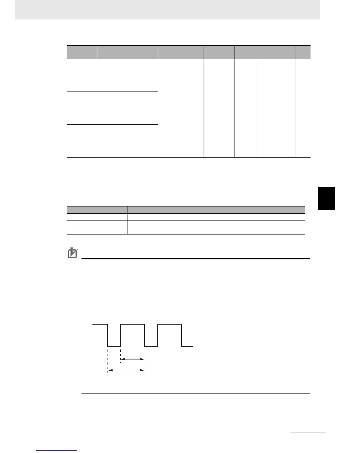
• The multi-function digital output (PWM output) MP terminal provides PWM signal outputs.
The terminal outputs the value of 0.00 to 100.00% (variable) as the pulse width (duty ratio
t/T) in a 6.4 ms cycle.
Function
variable
Description Data range
Default
data
Unit Data size R/W
YA(0) MX2 and RX:
Analog output terminal
variable
(MP terminal: 6.4 ms
cycle, PWM output)
0 to 10,000 0 0.01% Unsigned
1 word
R/W
YA(1) MX2 and RX:
Analog output terminal
variable
(AM terminal: 0 to 10 V
output)
YA(2) RX only:
Analog output terminal
variable
(AMI terminal: 4 to 20 mA
output)
Function variable Parameter Setting
YA(00) Set the MP Selection (C027) to 12 (Drive Programming: YA(0))
YA(01) Set the AM Selection (C028) to 13 (Drive Programming: YA(1))
YA(02) Set the AMI Selection (C029) to 14 (Drive Programming: YA(2))
t
T
 Loading...


