EN-8
Table 2 Control Circuit Terminals with default settings
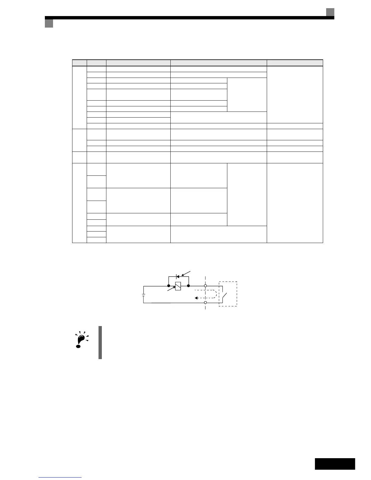
Fig 3 Flywheel Diode Connection
Sinking/Sourcing Mode (NPN/PNP Selection)
The input terminal logic can be switched over between sinking mode (0-V common, NPN) and sourcing mode
(+24V common, PNP) by using the jumper CN5. An external power supply is also supported, providing more
freedom in signal input methods.
Type No. Signal Name Function Signal Level
Dig-
ital
input
signals
S1 Forward run/stop command Forward run when ON; stopped when OFF.
24 VDC, 8 mA
Photo-coupler
S2 Reverse run/stop command Reverse run when ON; stopped when OFF.
S3 Nominal speed Nominal speed when ON.
Functions are
selected by setting
H1-01 to H1-05.
S4 Inspection Run Inspection RUN when ON.
S5 Intermediate speed
Intermediate speed when
ON.
S6 Leveling speed Leveling speed when ON.
S7 Not used –
BB Hardware baseblock Both inputs must be enabled to enable the inverter
outputBB1 Hardware baseblock 1
SC Digital input common – –
Ana-
log
input
signals
+V
15 V power supply
*1
*1. Do not use this power supply for supplying any external equipment.
15 V power supply for analog references
15 V
(Max. current: 20 mA)
A1 Frequency reference 0 to +10 V/100% 0 to +10 V(20 kΩ)
AC Analog reference neutral – –
E(G)
Shield wire, optional ground line
connection point
––
Dig-
ital
output
signals
M1
Brake command
(1NO contact)
Brake command when ON.
Multi-function con-
tact outputs
Relay contacts
Contact capacity:
1 A max. at 250 VAC
1 A max. at 30 VDC
*2
*2. When driving a reactive load, such as a relay coil with DC power supply, always insert a flywheel diode as shown in Fig 3.
M2
M3
Contactor Control
(1NO contact)
Contactor Control when ON
M4
M5
Inverter Ready
(1NO contact)
Inverter Ready when ON.
M6
MA
Fault output signal (SPDT)
(1 Change over contact)
Fault when CLOSED across MA and MC
Fault when OPEN across MB and MC
MB
MC
1. In Fig 4 the wiring of the digital inputs S1 to S7 and BB, BB1 is shown for the connection of contacts or NPN
transistors (0V common and sinking mode). This is the default setting.
For the connection of PNP transistors or for using a 24V external power supply, refer to Ta ble 3.
2. A DC reactor is an option only for Inverters of 18.5 kW or less. Remove the short circuit bar when connecting a
DC reactor.
External power: 30
VDC max.
Coil
Flywheel diode
1 A max.
The rating of the flywheel diode must
be at least as high as the circuit volt-
age.
IMPORTANT
 Loading...


