EN-20
Speed Selection Table
The following table shows the combinations of the digital input and the according speed.
If b1-02 is set to “1”, frequency reference 1 is input as analog reference at terminal A1.
Separate Speed Selection Inputs, High Speed Has Priority (d1-18=1)
With this setting 6 different speeds (defined in the parameters d1-09 to d1-17) can be set and selected using
four digital inputs.
Digital Input Factory Settings
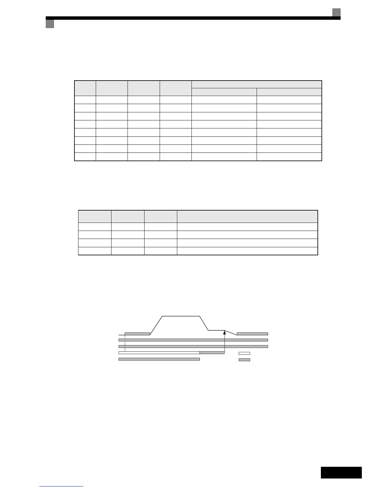
Higher Speed has Priority and a Leveling Speed Input is Selected (H1-=83)
If d1-18 is set to 1 and one multi-function digital input is set to leveling speed selection (H1-=83), the
inverter decelerates to the leveling speed (d1-17) when the selected speed signal is removed. Inspection Speed
can not be selected as travel speed. The higher speed has priority over the leveling speed, i.e. as long as a
higher speed is selected, the leveling signal is disregarded (see the fig. below)
The inverter stops when the leveling signal or the Up/Down signal is removed.
Higher Speed Priority is Selected and a Leveling Speed Input is Not Selected (H1-K83)
When the leveling speed command is not selected for any digital input, the inverter decelerates to the leveling
speed (d1-17) when the selected speed signal is removed. Inspection Speed can not be selected as travel speed
To select the leveling speed as travel speed the frequency reference loss detection must be disabled (S3-09=0).
The inverter stops when the direction signal Up/Down is removed.
Speed
Multi-step
Speed Com-
mand 1
Multi-step
Speed Com-
mand 2
Multi-step
Speed Com-
mand 3
Selected Frequency
d1-18 = 0 d1-18 = 3
1 OFF OFF OFF Frequency reference 1 d1-01 Stop
2 ON OFF OFF Frequency reference 2 d1-02 Frequency reference 2 d1-02
3 OFF ON OFF Frequency reference 3 d1-03 Frequency reference 3 d1-03
4 ON ON OFF Frequency reference 4 d1-04 Frequency reference 4 d1-04
5 OFF OFF ON Frequency reference 5 d1-05 Frequency reference 5 d1-05
6 ON OFF ON Frequency reference 6 d1-06 Frequency reference 6 d1-06
7 OFF ON ON Frequency reference 7 d1-07 Frequency reference 7 d1-07
8 ON ON ON Frequency reference 8 d1-08 Frequency reference 8 d1-08
Terminal
Parameter
Number
Set Value Details
S3 H1-01 80 Nominal speed selection (d1-09)
S4 H1-02 84 Inspection speed selection (d1-14)
S5 H1-03 81 Intermediate speed selection (d1-10)
S6 H1-04 83 Leveling speed selection (d1-17)
Up/Donw
Leveling speed
Selected speed
Speed
DC Injection/
zero servo
DC Injection/
zero servo
Input is set
No effect
Hardware BB
 Loading...


