EN-25
FF_CAL
Feed forward motor acceleration time active
• Perform the complete tuning procedure
• Abort the tuning by setting
n5-05 = 0.
FRL
Ref Missing
No speed was selected before the inverter start. Check the speed selection/start sequence.
GF
Ground Fault
The ground current at the Inverter output exceeded
50% of the Inverter rated output current and L8-09=1
(Enabled).
• Remove the motor and run the Inverter without the
motor.
• Check the motor for a phase to ground short.
• Check the output current with a clampmeter to ver-
ify the DCCT reading.
• Check the control sequence for wrong motor contac-
tor signals.
LF
Output Phase
Loss
An open-phase occurred at the Inverter output.
The fault is detected when the output current falls
below 5% of the inverter rated current and L8-07=1
• Reset the fault after correcting its cause.
• Check the motor and Inverter capacity.
OC
Over Current
The Inverter’s output current exceeded the over cur-
rent detection level.
• Remove the motor and run the Inverter without the
motor.
• Check the motor for a phase-to-phase short.
• Verify the accel/decel times
•(C1-).
• Check the Inverter for a phase-to-phase short at the
output.
OH
Heatsink Over-
temp
L8-03 = 0,1 or 2 and the temperature of the Inverter's
cooling fin exceeded the L8-02 value.
• Check for dirt build-up on the fans or heatsink.
• Reduce the ambient temperature around the drive.
• Replace the cooling fan(s).
Inverter's Cooling Fan Stopped
L8-03 = 3 and the temperature of the Inverter's cool-
ing fin exceeded the L8-02 value.
OH1
Heatsink Max
Temp
The temperature of the Inverter’s heatsink exceeded
105 °C.
• Check for dirt build-up on the fans or heatsink.
• Reduce the ambient temperature around the drive.
• Replace the cooling fan(s).
Inverter’s Cooling Fan Stopped
OL1
Motor Overload
Detected when L1-01 is set to 1,2 or 3 and the
Inverter’s output current exceeded the motor over-
load curve.
The overload curve is adjustable using parameter E2-
01 (Motor Rated Current), L1-01 (Motor Protection
Selection) and L2-02 (Motor Protection Time Con-
stant)
• Recheck the cycle time and the size of the load as
well as the accel/decel times
•(C1-).
• Check the V/f characteristics (E1-).
• Check the setting of Motor Rated Current Setting
(E2-01).
OL2
Inv Overload
The Inverter output current exceeded the Inverter’s
overload capability.
• Recheck the cycle time and the size of the load as
well as the accel/decel times
•(C1-).
• Check the V/f characteristics (E1-).
• Check the setting of Motor Rated Current Setting
(E2-01).
OS
Motor Over speed
Det
F1-03 = 0, 1 or 2 and A1-02 is set to 3 or 6.
The motor speed feedback (U1-05) exceeded the F1-
08 value for the time F1-09.or longer.
• Adjust the ASR settings in the C5 parameter group.
• Check the reference circuit and reference gain.
• Check the settings in F1-08 and F1-09.
F1-03 = 3 and A1-02 is set to 3 or 6.
The motor speed feedback (U1-05) exceeded the F1-
08 value for the time F1-09.or longer.
OV
DC Bus Overvolt
(only in
stop
condi-
tion)
The DC bus voltage has exceeded the overvoltage
detection level.
Default detection levels are:
200 V class: 410 VDC
400 V class: 820 VDC
• Increase the deceleration time (C1-02/04/06/08) or
connect a braking option.
• Check the power supply and decrease the voltage to
meet the inverter’s specifications.
• Check the braking chopper/resistor.
PF
Input Phase Loss
Too big DC bus voltage ripple.
Only detected when L8-05=1 (enabled)
• Tighten the input terminal screws
• Check the power supply voltage
PGO
PG Open
(PG Disconnec-
tion)
F1-02 = 0, 1 or 2 and A1-02 = 3 or 6
No PG (encoder) pulses are received for the time F1-
14 or longer.
• Fix the broken/disconnected wiring.
• Fix the wiring.
• Supply power to the PG
•properly.
• Check the sequence and if the brake is opened when
the inverter starts to increase the speed.
F1-02 = 3 and A1-02 = 3 or 6.
No PG (encoder) pulses are received for the time F1-
14 or longer.
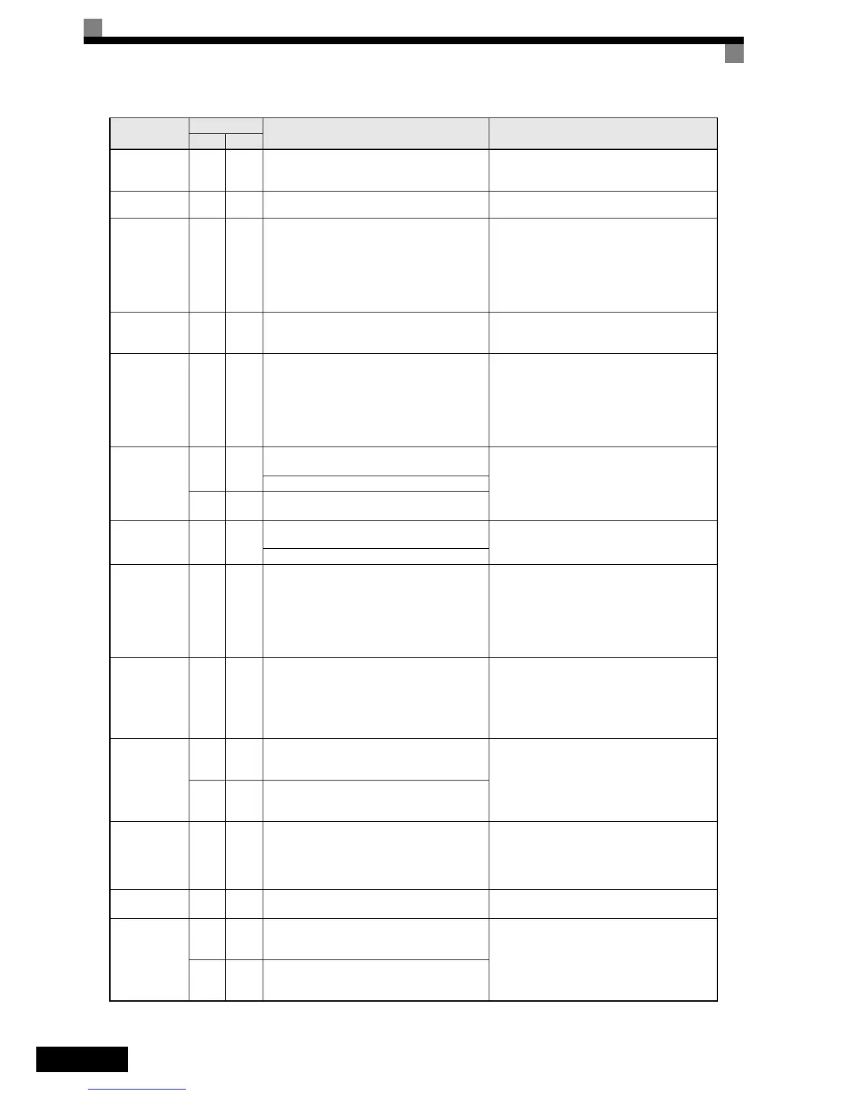
Display
Displayed as
Meaning Corrective Actions
Alarm Fault
 Loading...


