EasyManua.ls Logo

Omron CS1W-AD081-V1 User Manual

Omron CS1W-AD081-V1
427 pages
To Next Page IconTo Next Page
To Previous Page IconTo Previous Page
Page #393 background imageLoading...
Page #393 background image
370
Sample Programs Appendix B
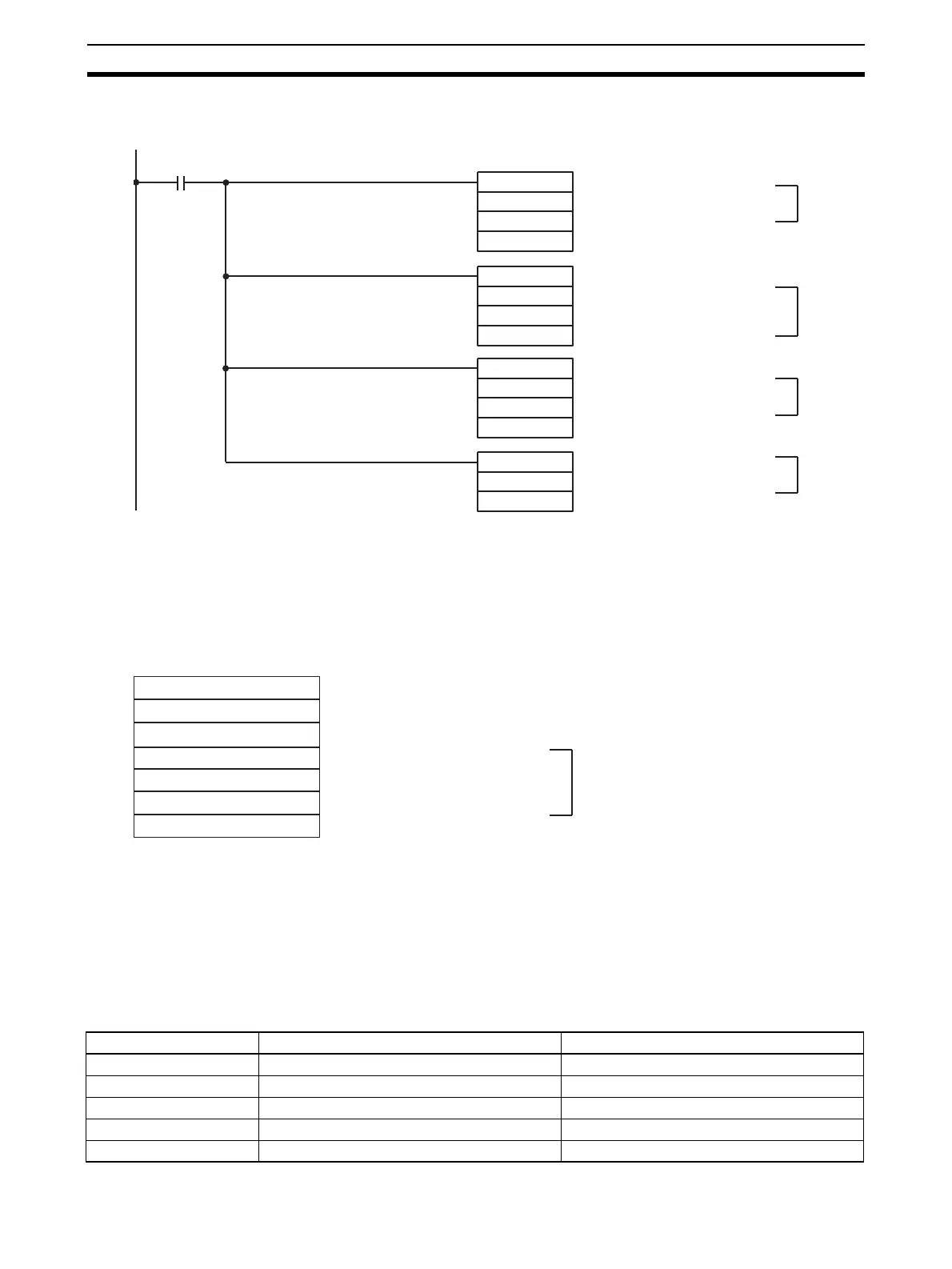
Program Example
Data Flow (Unit Number 0): Word 2001 (A/D Conversion Value)
Word 0200 (Calculation Result)
(1) The negative number portion is added to the conversion value (word 2001).
(2) The binary data is scaled to a range of 0 to 4000.
(3) The scaling results are multiplied by 4400.
(4) The square root is calculated, and the result is output to word 0200.
DM Area Settings
Input signal range: 0 to 10 V / 1 to 5 V / 4 to 20 mA
If the result of the binary-to-BCD conversion is negative, an error will be generated by the ROOT(072) instruc-
tion.
With a signal range of –10 to 10 V, scaling is executed by augmenting the negative portion (–10 V –5%). In this
program example, the value of D00000 is converted to 0898. Refer to Scaling on page 366 for details.
Mean Value Processing
Data is taken for the set number of samplings and the mean value is calculated.
Unit Settings
+(400)
2001
D00000
D00001
ROOT(072)
D00006
0200
SCL(194)
D00001
D00002
D00006
*B(424)
D00006
#4400
D00006
Execution condition
Conversion value +
Negative number
Scaling is executed using
augmented value. Result is
output to word D00006.
Result of step #2 (above)
is multiplied by 4400.
Square root is calculated, and
result is output to word 0200.
(1)
(2)
(3)
(4)
D00000: 00C8
D00001: (Used for calculation)
D00002: 0000
D00003: 0000
D00004: 4400
D00005: 1130
D00006: (Used for calculation)
Digital value for 5%
Conversion value +C8 (5% portion)
Lower limit: BCD
Lower limit +C8 (5% portion): Binary
Upper limit: BCD
Upper limit +C8 (5% portion): Binary
Used with SCL(194)
instruction
Item Setting contents Actual settings
Unit CS1W-AD081-V1 ---
Unit number #0 Unit number switch: 00
Operation mode Normal mode Back-panel DIP switch: All OFF
Input number Input 1 used D20000 = 0001
Input signal range Input number 1, 0 to 10 V D20001 = 0001

Table of Contents

Questions and Answers:

Omron CS1W-AD081-V1 Specifications

General IconGeneral
Number of Channels8
Power Supply5 V DC
Operating Temperature0 to 55 °C
TypeAnalog Input
Input Range0 to 10 V, 0 to 20 mA, 4 to 20 mA
Sampling Time/Conversion Time1ms per channel
Current Consumption100 mA
IsolationPhotocoupler isolation between input and internal circuit
Storage Temperature-25 to 65 °C
Relative Humidity35 to 85% (with no condensation)
Noise Immunity±2 kV
StandardsCE, UL

Summary

SYSMAC CS/CJ Series

Analog I/O Units

Describes the types of analog I/O units covered in the manual, including input, output, and combined units.

PRECAUTIONS

General Precautions

Fundamental safety and operational guidelines for using OMRON products.

Safety Precautions

Critical safety warnings and procedures to prevent injury or damage.

Application Considerations

SECTION 2 CS-series Analog Input Units

2-2 Operating Procedure

Step-by-step instructions for operating CS-series Analog Input Units.

2-6 Analog Input Functions and Operating Procedures

Details on analog input functions and their operational procedures.

2-8 Handling Errors and Alarms

Troubleshooting guide for errors and alarms in Analog Input Units.

SECTION 3 CJ-series Analog Input Units

3-2 Operating Procedure

Step-by-step instructions for operating CJ-series Analog Input Units.

3-6 Analog Input Functions and Operating Procedures

Details on analog input functions and their operational procedures.

3-8 Handling Errors and Alarms

Troubleshooting guide for errors and alarms in Analog Input Units.

SECTION 4 CS-series Analog Output Units

4-2 Operating Procedure

Step-by-step instructions for operating CS-series Analog Output Units.

4-6 Analog Output Functions and Operating Procedures

Details on analog output functions and their operational procedures.

4-8 Handling Errors and Alarms

Troubleshooting guide for errors and alarms in Analog Output Units.

SECTION 5 CJ-series Analog Output Unit

5-2 Operating Procedure

Step-by-step instructions for operating CJ-series Analog Output Units.

5-6 Analog Output Functions and Operating Procedures

Details on analog output functions and their operational procedures.

5-8 Handling Errors and Alarms

Troubleshooting guide for errors and alarms in Analog Output Units.

SECTION 6 CS-series Analog I/O Unit

6-2 Operating Procedure

Step-by-step instructions for operating CS-series Analog I/O Units.

6-6 Analog Input Functions and Operating Procedures

Details on analog input functions and their operational procedures.

6-7 Analog Output Functions and Operating Procedures

Details on analog output functions and their operational procedures.

6-10 Handling Errors and Alarms

Troubleshooting guide for errors and alarms in Analog I/O Units.

SECTION 7 CJ-series Analog I/O Unit

7-2 Operating Procedure

Step-by-step instructions for operating CJ-series Analog I/O Units.

7-6 Analog Input Functions and Operating Procedures

Details on analog input functions and their operational procedures.

7-7 Analog Output Functions and Operating Procedures

Details on analog output functions and their operational procedures.

7-10 Handling Errors and Alarms

Troubleshooting guide for errors and alarms in Analog I/O Units.

Appendix B Sample Programs

Appendix C Data Memory Coding Sheets

Related product manuals