107
Exchanging Data with the CPU Unit Section 5-1
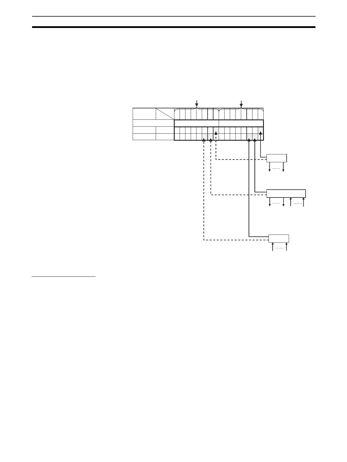
• Participation Flags are allocated the rightmost byte (bits 00 to 07). Inputs
are allocated after outputs.
• Communications Error Flags are allocated the leftmost byte (bits 08 to
15).
Registration Tables
Overview Registration Tables are used to register Slave Units that are intended to par-
ticipate at particular node addresses (along with the models corresponding to
the node addresses) to enable verifying that they actually are participating. At
the same time, they prevent unregistered Slave Units and Slave Units of the
wrong models from participating in the network.
151413121110987654321 0
7654321076543210
765432 10765432 10
Bit
Address
CIO 2018
Example for Mode 0
I/O Memory (Allocated in the Special I/O Unit Area in the CIO Area)
CIO 2019
Communications Error Flags for
nodes 0 to 7, both inputs and
outputs, are allocated bits 8 to 15.
Participation Flags for nodes 0
to 7, both inputs and outputs,
are allocated bits 0 to 7.
Output/input
For outputs
For inputs
Communications Error Flags
Participation Flags
Output Slave Unit
Node address 0
Slave Unit
Slave Unit
Slave Unit
16 outputs
Input Slave Unit
Node address 1
16 outputs
16 inputs
Note: When there are both inputs and
outputs, flags are allocated only
for the input nodes.
Input Slave Unit
Node address 2
16 inputs