28
Design and Operating Procedure Examples Section 1-6
• Communications Error Communications Stop Mode (Stopping All Remote
I/O Communications when a Communications Error Occurs in One Slave
Unit) and Registration Table Enable Setting
4. Set the unit number on the front of the Master Unit.
The unit number is set to 5 in this example. Therefore the first address is
CIO 2050.
5. Set the Slave Unit node addresses.
6. Connect the CX-Integrator to the CPU Unit's serial communications port.
7. Turn ON the power to the PLC.
8. Connect the CX-Integrator online and edit and download the Master Unit
device parameters.
(1) Connect online to the PLC where the Master Unit is mounted.
(2) In the Online Connection Information Window, right-click the Master
Unit under the connected PLC, and then select Connect.
(3) Right-click the Master Unit under the connected PLC, and select Trans-
fer [Network to Computer].
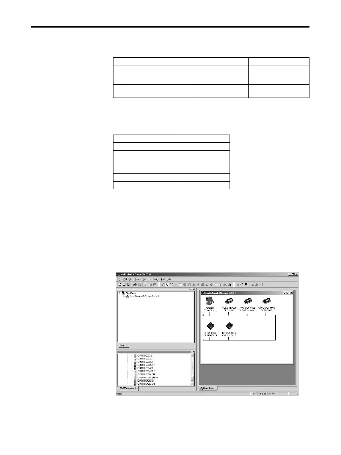
(4) Double-click the Master Unit in the Network Configuration Window.
Then, on the General Master Unit Tab Page, select the Slave Units to
be registered and create a Registration Table.
SW Name ON OFF
3 ESTP (Communications
Error Communications
Stop Mode)
Communications stop
when a communications
error occurs.
Communications do not
stop when a communica-
tions error occurs.
4 REGS (Registration
Table Enable Setting)
Registration Table
enabled.
Registration Table dis-
abled.
Model Node address
CRT1-ID16 Node address #0
CRT1-ID16 + XWT-OD08 Node address #1
CRT1-OD16 Node address #2
CRT1B-ID02S Bit node address #0
CRT1B-ID02S Bit node address #1
CRT1B-OD02S Bit node address #2