62
Installation Section 4-1
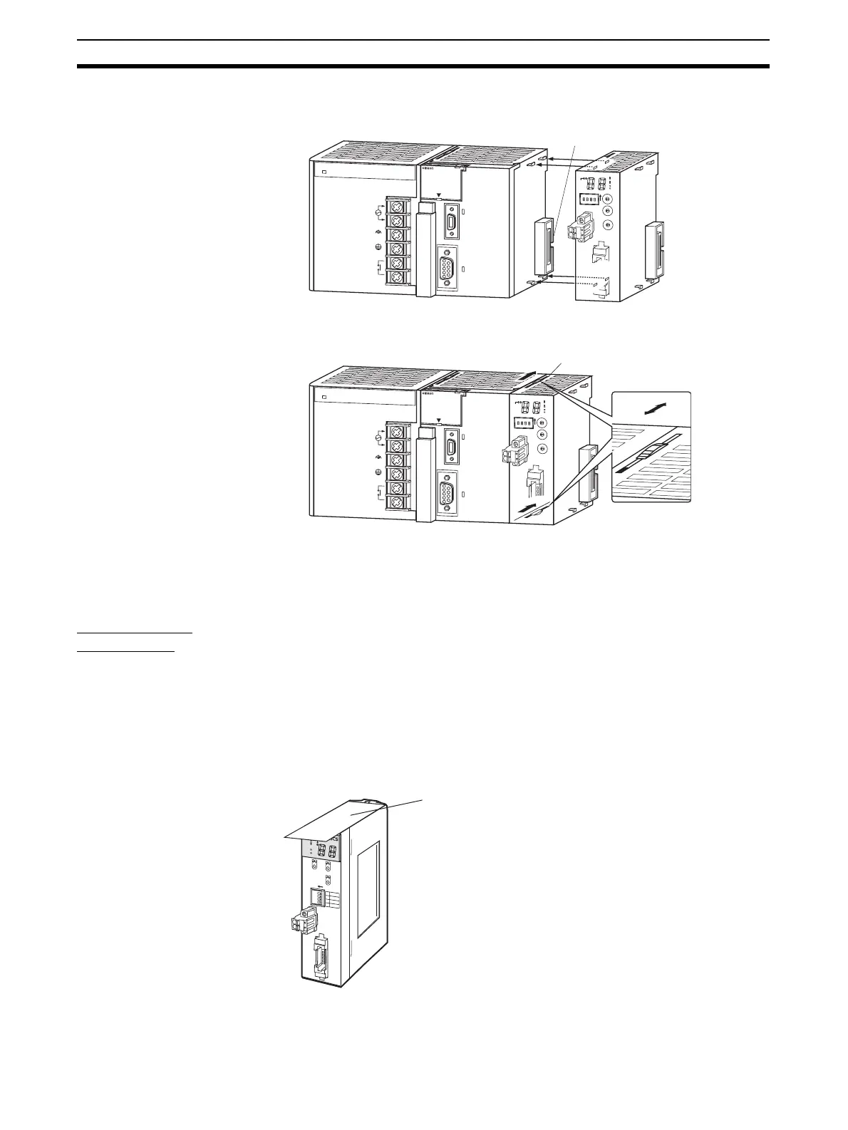
CJ-series Master Unit
1,2,3... 1. Align the connectors and connect the Master Unit.
2. Slide the yellow sliders at the top and bottom of the Unit until they click into
place and lock the Unit.
Note If the sliders are not locked completely, the Master Unit may not function prop-
erly.
To remove the Unit, unlock the sliders and remove the Unit.
Unit Handling
Precautions
• Always turn OFF the power supply to the PLC before performing any wir-
ing operations on the Unit.
• To prevent noise from affecting the system, place all wires connected to
the Unit ports in ducts, and use separate ducts from those used for high-
voltage and high-power lines.
• Wire with the sheets on top of the Units in place to prevent pieces of wire
from entering the Unit. Remove the sheets after completing wiring to facil-
itate cooling.
CS-series Master Unit
P
A
2
0
5R
POWER
INPUT
AC100-24
0V
L
2
/N
L
1
DC24V
AC240V
OUTPUT
RUN
P
E
R
IP
H
E
R
A
L
E
R
R
/A
LM
R
U
N
IN
H
C
O
M
M
P
R
P
H
L
CONTROL
L
ER
C
J1
G
-C
P
U
4
4
S
Y
S
M
A
C
PROGRAMM
ABLE
PORT
O
P
E
N
B
U
S
Y
M
C
P
W
R
CRM21
+
10
0
M
S
N
S
S
D
R
D
M
A
C
H
N
o
.
M
O
D
E
X
1
0
1
O
N
X
1
0
0
B
S
+
BS-
D
C
2
4
V
IN
P
U
T
B
S
+
B
D
H
D
B
L
B
S
-
SW
1
2
3
4
1
2
3
4
0
1
2
3
4
5
6
7
8
9
0
1
2
3
4
5
6
7
8
9
0
1
2
3
4
5
6
7
8
9
N
E
T
W
O
R
K
P
S
Connector
P
A
2
0
5
R
POWER
INPUT
AC100-24
0V
L
2
/N
L
1
DC24V
AC240V
OUTPUT
RUN
P
E
R
IP
H
E
R
A
L
E
R
R
/A
L
M
R
U
N
IN
H
C
O
M
M
P
R
P
H
L
CONTROL
L
ER
C
J
1
G
-C
P
U
4
4
S
Y
S
M
A
C
PROGRAM
M
ABLE
PORT
O
P
E
N
B
U
S
Y
M
C
P
W
R
Slider
B
S
+
B
D
H
D
B
L
B
S
-
CRM21
+10
0
M
S
N
S
S
D
R
D
M
A
C
H
N
o
.
M
O
D
E
X
1
0
1
O
N
X
1
0
0
BS+
B
S
-
D
C
2
4
V
IN
P
U
T
SW
1
2
3
4
1
2
3
4
0
1
2
3
4
5
6
7
8
9
0
1
2
3
4
5
6
7
8
9
0
1
2
3
4
5
6
7
8
9
N
E
T
W
O
R
K
P
S
Lock
Unlock
CRM21
M
S
NS
S
D
R
D
+
1
0
0
MACH
No.
X10
1
MODE
ON
X10
0
1234
ON ↓
1
DR0
2
DR1
3
ESTP
4
R
E
G
S
N
E
T
W
O
R
K
P
O
W
E
R
S
U
P
P
L
Y
DC24V
INPUT
B
S
+
B
S
+
B
D
H
B
D
L
B
S
-
B
S
-
Remove the sheet after
completing wiring.