2 - 17
2 Preparations
Digital Temperature Controllers (Simple Type) User’s Manual (H211)
2-2 Using the Terminals
2
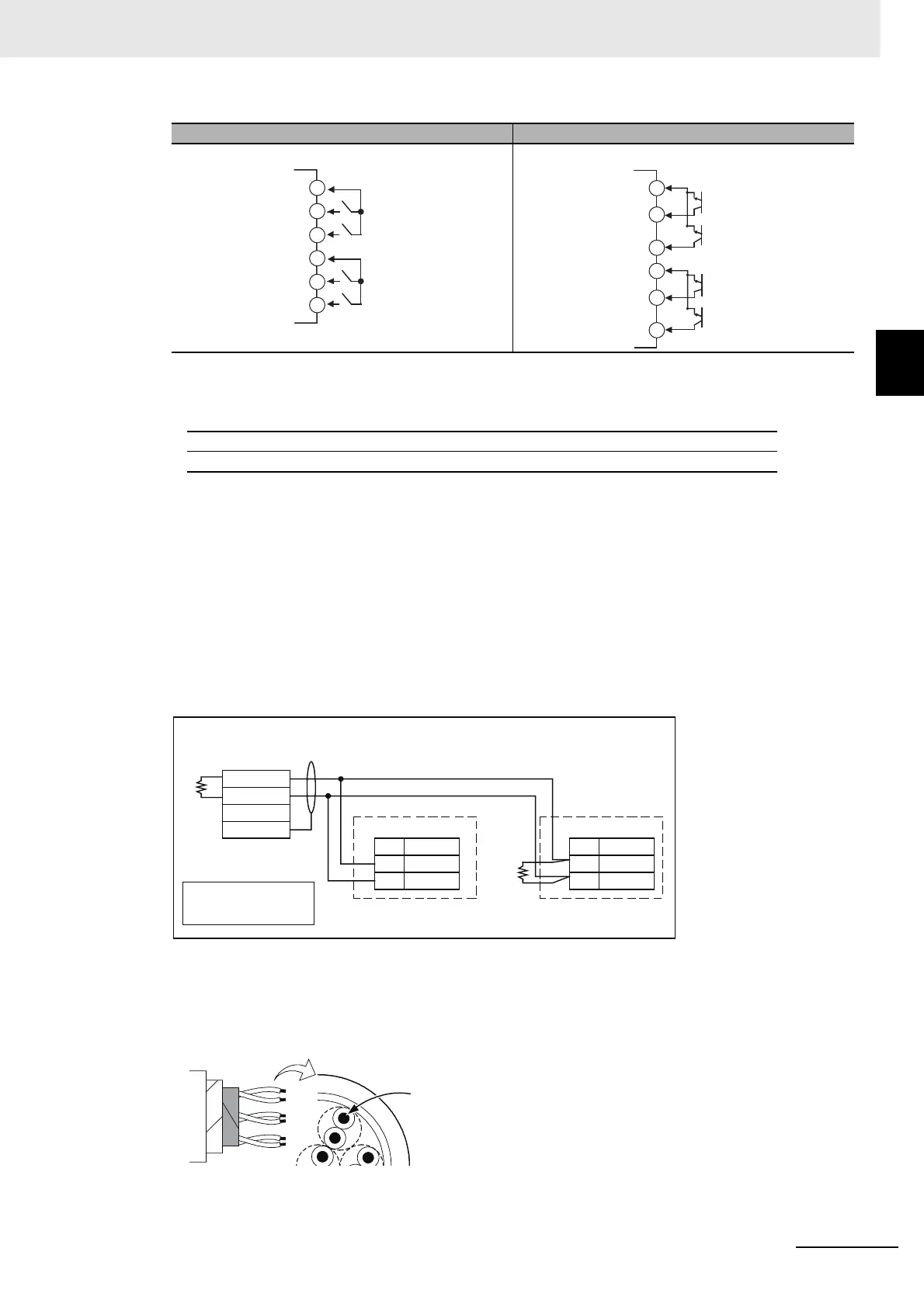
2-2-4 Wiring
• Use event inputs under the following conditions:
• The outflow current is approximately 7 mA.
z CT Input
E5CC/E5EC models with an option number of 801, 802, 808, or 810 have one CT input.
z Communications
RS-485
E5CC/E5EC models with an option number of 802, 804, 808, or 810 support communications. Connect the
communications cable to terminals 13 and 14 to use communications with the E5CC/E5EC.
Communications Unit Connection Diagram
● E5CC/E5EC
• The RS-485 connection can be either one-to-one or one-to-N. A maximum of 32 Units (including
the host computer) can be connected in one-to-N systems. The maximum total cable length is
500 m. Use a shielded, AWG24 to AWG18 (cross-sectional area of 0.205 to 0.823 mm
2
)
twisted-pair cable.
Option number: 810
Contact input ON: 1 kΩ max., OFF: 100 kΩ min.
No-contact input ON: Residual voltage of 1.5 V max.; OFF: Leakage current of 0.1 mA max.
Contact inputs Non-contact inputs
EV1
EV2
EV3
EV4
18
16
17
15
13
14
EV3
EV4
EV1
EV2
+
+
−
+
+
−
18
16
17
15
13
14
No.
14
13
No.
14
13
RS-485
E5CC/E5EC (No.1)
RS-485
E5CC/E5EC (No.31)
100 Ω
A (−)
B (+)
A (−)
B (+)
−
+
FG
RS-485
Host computer
Shield
Terminator (120 Ω, 1/2 W)
Abbreviation
Abbreviation
A < B: [1] Mark
A > B: [0] Space
Cross-sectional area of
conductor
AWG24: 0.205 mm
2
AWG18: 0.823 mm
2