272
Appendix
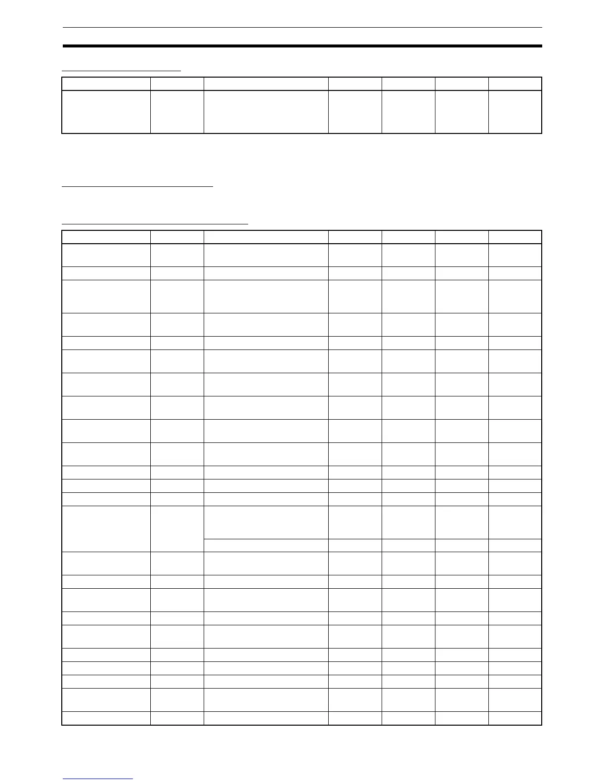
Manual Control Level
Note When the Manual MV Limit Enable parameter is set to ON, the setting range will be the MV lower limit to
the MV upper limit.
Monitor/Setting Item Level
The contents displayed vary depending on the Monitor/Setting 1 to 5 (advanced function setting level) setting.
Advanced Function Setting Level
Parameters Characters Setting (monitor) value Display Default Unit Set value
Manual MV −5.0 to 105.0 (standard) (See
note.)
−105.0 to 105.0 (heating/cool-
ing) (See note.)
0.0 %
Parameters Characters Setting (monitor) value Display Default Unit Set value
Parameter Initializa-
tion
init OFF, FACT off, fact OFF None
Multi-SP Uses mspu OFF, ON off, on OFF None
SP Ramp Time Unit spru S: EU/second
M: EU/minute
H: EU/hour
s
m
h
MNone
Standby Sequence
Reset
rest Condition A, condition B a, b Condition A None
HB ON/OFF hbu OFF, ON off, on ON None
Auxiliary Output 1
Open in Alarm
sb1n N-O: Close in alarm
N-C: Open in alarm
n-o, n-c N-O None
Auxiliary Output 2
Open in Alarm
sb2n N-O: Close in alarm
N-C: Open in alarm
n-o, n-c N-O None
Auxiliary Output 3
Open in Alarm
sb3n N-O: Close in alarm
N-C: Open in alarm
n-o, n-c N-O None
Heater Burnout
Latch
hbl OFF, ON off, on OFF None
Heater Burnout Hys-
teresis
hbh 0.1 to 50.0 0.1 A
ST Stable Range st-b 0.1 to 999.9 15.0 °C or °F
α alfa 0.00 to 1.00 0.65 None
AT Calculated Gain at-g 0.1 to 10.0 0.8 None
AT H y s te r e s i s at-h Universal input: 0.1 to 999.9 0.8 °C or °F
(See note
1.)
Analog input: 0.01 to 9.99 0.20 %FS
Limit Cycle MV
Amplitude
lcma 5.0 to 50.0 20.0 %
Input Digital Filter inf 0.0 to 999.9 0.0 Second
Additional PV Dis-
play
pvad OFF, ON off, on OFF None
MV Display o-dp OFF, ON off, on OFF None
Automatic Display
Return Time
ret OFF or 1 to 99 off, 1 to
99
OFF Second
Alarm 1 Latch a1lt OFF, ON off, on OFF None
Alarm 2 Latch a2lt OFF, ON off, on OFF None
Alarm 3 Latch a3lt OFF, ON off, on OFF None
Move to Protect
Level Time
prlt 1 to 30 3 Second
Input Error Output sero OFF, ON off, on OFF None