274
Appendix
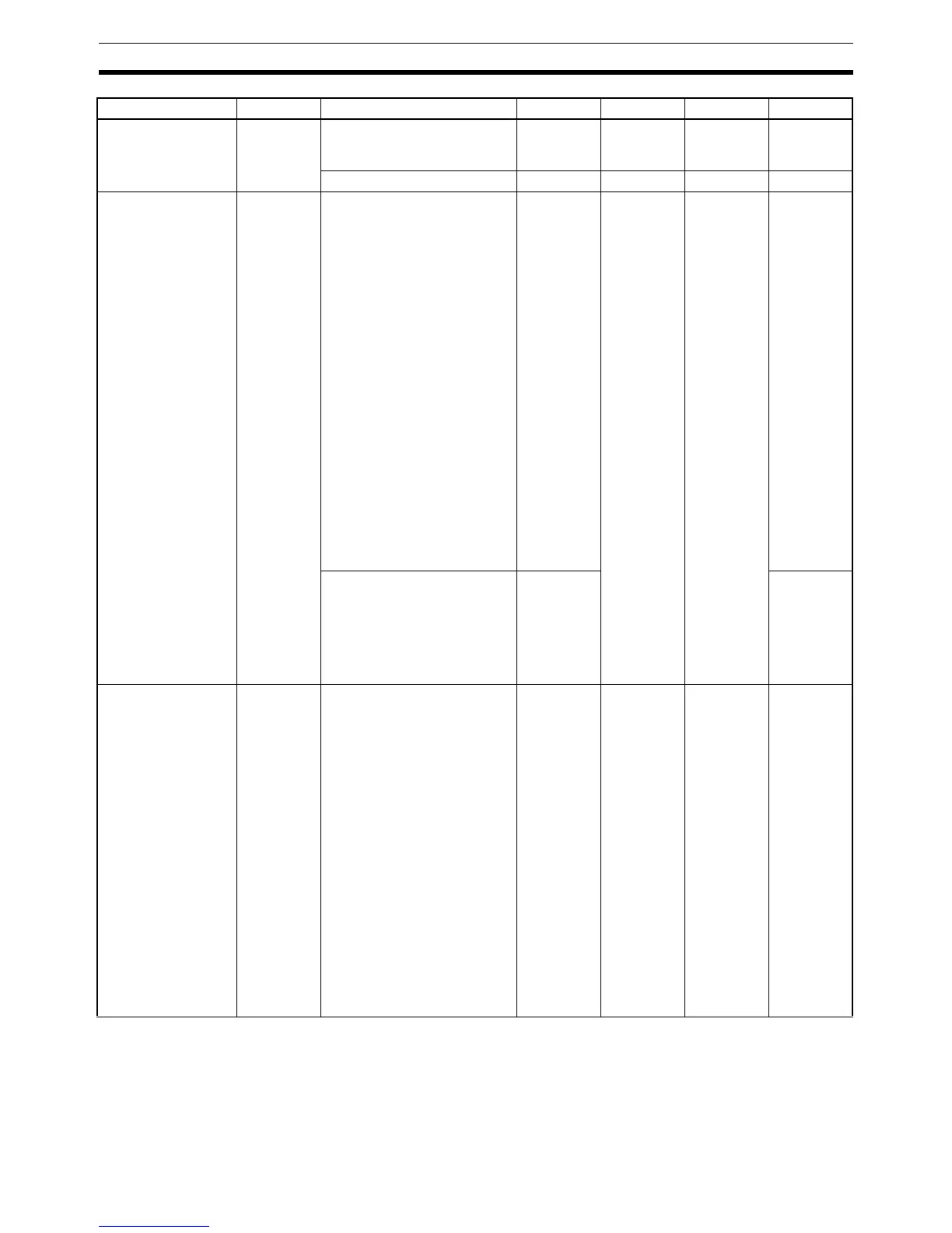
LBA Band lbab Universal input: 0.0 to 999.9 3.0 °C or °F
(See note
1.)
Analog input: 0.00 to 99.99 0.20 %FS
Control Output 1
Assignment
out1 When control output 1 is a
voltage output (for driving
SSR) (See note 2.):
NONE: No assignment
O: Control output (heat-
ing)
C-O: Control output (cool-
ing)
ALM1: Alarm 1
ALM2: Alarm 2
ALM3: Alarm 3
P.END: Program end output
(See note 3.)
RALM: Control output ON/
OFF count alarm
(See note 4.)
WR1: Work bit 1 (See note 5.)
WR2: Work bit 2 (See note 5.)
WR3: Work bit 3 (See note 5.)
WR4: Work bit 4 (See note 5.)
WR5: Work bit 5 (See note 5.)
WR6: Work bit 6 (See note 5.)
WR7: Work bit 7 (See note 5.)
WR8: Work bit 8 (See note 5.)
none
o
c-o
alm1
alm2
alm3
p.end
ralm
wr1
wr2
wr3
wr4
wr5
wr6
wr7
wr8
ONone
When control output 1 is a
current output (See note 2.):
NONE: No assignment
O: Control output (heat-
ing)
C-O: Control output (cool-
ing)
none
o
c-o
Control Output 2
Assignment
out2 NONE: No assignment
O: Control output (heat-
ing)
C-O: Control output (cool-
ing)
ALM1: Alarm 1
ALM2: Alarm 2
ALM3: Alarm 3
P.END: Program end output
(See note 3.)
RALM: Control output ON/
OFF count alarm
(See note 4.)
WR1: Work bit 1 (See note 5.)
WR2: Work bit 2 (See note 5.)
WR3: Work bit 3 (See note 5.)
WR4: Work bit 4 (See note 5.)
WR5: Work bit 5 (See note 5.)
WR6: Work bit 6 (See note 5.)
WR7: Work bit 7 (See note 5.)
WR8: Work bit 8 (See note 5.)
none
o
c-o
alm1
alm2
alm3
p.end
ralm
wr1
wr2
wr3
wr4
wr5
wr6
wr7
wr8
NONE None
Parameters Characters Setting (monitor) value Display Default Unit Set value