91
F3SJ-E/B
User’s Manual
Chapter4 Input/Output Circuit
Input/Output Circuit and Applications
E
Basic Type
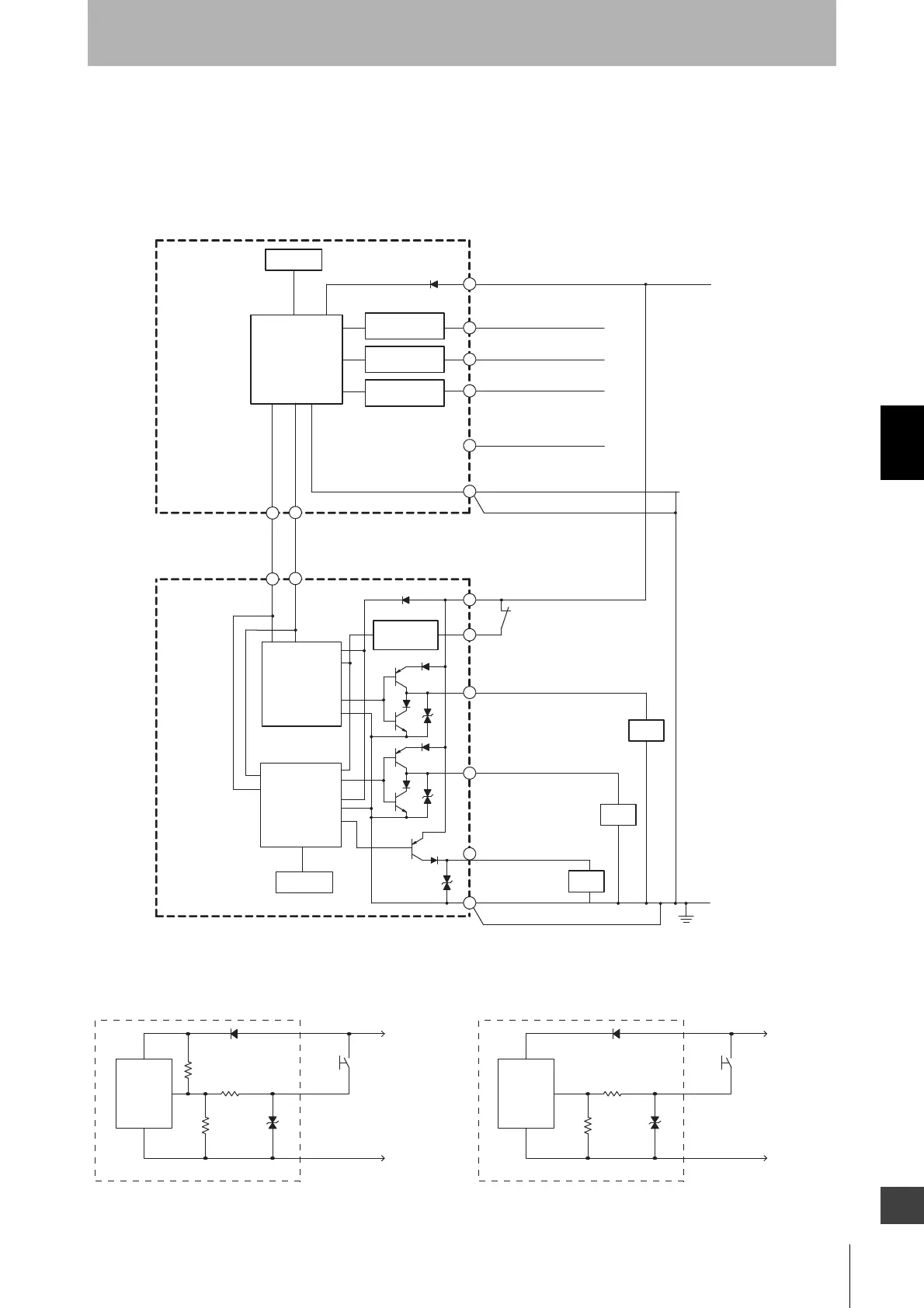
Entire circuit diagram
The entire circuit diagram of the Basic Type is shown below.
The numbers in the circles indicate the connector's pin numbers.
The names in the brackets [ ] indicate signal names for muting system.
Input circuit diagram by function
The input circuit diagrams of the Basic Type by function are shown below.
2
8
3
4
5
5 6
7
1
+24 VDC
2
3
1
4
Brown
Black
Test input
White
Yellow
Blue
Brown
Red
White
Safety output 2
Black
Yellow
Auxiliary output
Blue
7
Interlock select input
[Muting input 1]
Interlock Select
Input Circuit
Reset input
Reset Input
Circuit
External Device
Monitoring Input
Circuit
External device
monitoring input
0 V
8
Red
Not used
[Muting input 2]
6
Load
Shield
Shield
Indication
Emitter
Main Circuit
Test Input
Circuit
PinkGray
Pink
Communication line (+)
Gray
Communication line (-)
Receiver
Main Circuit 2
Receiver
Main Circuit 1
Indication
Safety output 1
Load
Load
Emitter
Main
Circuit
+24 VDC
0 V
Short circuit current:
3 mA
<Input circuit (Test, Reset or Interlock Select input)>
Receiver
Main
Circuit
+24 VDC
0 V
Short circuit current:
5 mA
<Input circuit (external device monitoring input)>