41
F3SJ-E/B
User’s Manual
Chapter3 Installation Conditions
Wiring/Installation
E
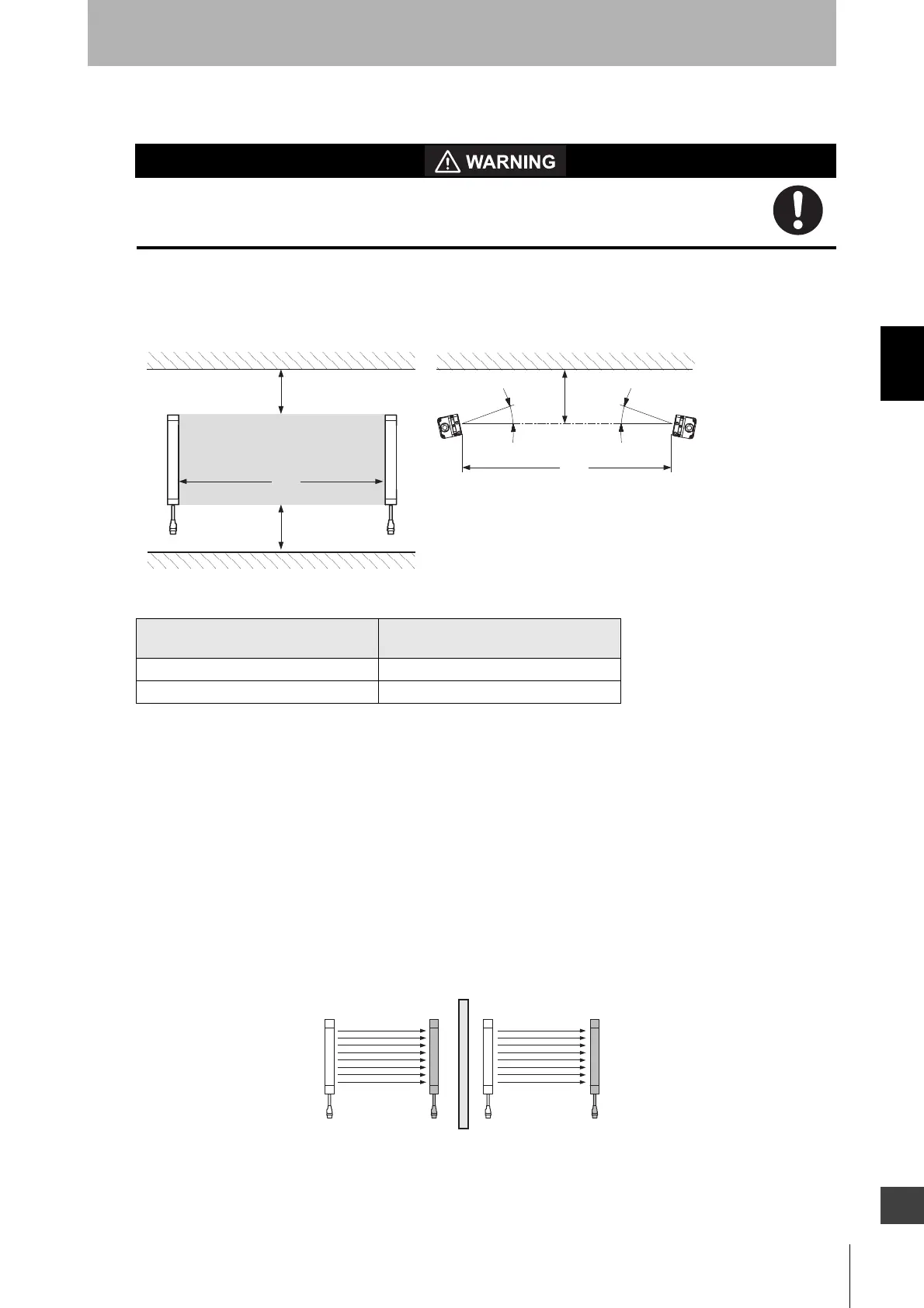
Distance from Reflective Surfaces
Install the sensor system so that it is not affected by reflection from a glossy surface.
Failure to do so may hinder detection, resulting in serious injury.
Install the sensor system at distance D or further from highly reflective surfaces such as metallic walls,
floors, ceilings, or workpieces, as shown below.
Mutual Interference Prevention
Mutual interference is prevented in up to three sets, using interference light detection and cycle shift
algorithm.
If four or more sets of F3SJ-E/Bs are installed, arrange them so that mutual interference does not
occur. If two sets are installed near each other, reflection from the surface of the F3SJ-E/B may cause
mutual interference. When mutual interference occurs, the safety outputs are turned OFF in a moment
or the F3SJ-E/B enters lockout state.
Combining countermeasures 1 to 3 shown below is effective.
1. Install a physical barrier between two sets
Distance between an emitter and a
receiver (operating range L)
Allowable installation distance D
0.2 to 3 m 0.13 m
More than 3 m L/2 x tan5° = L x 0.044 (m)
L
D
Detection zone
D
Emitter
Receiver
Reflective ceiling
Reflective floor
L
D
Emitter
Receiver
5°
Reflective surface
5°
Emitter Receiver Emitter Receiver